SRS Warning Light Remains ON
Circuit diagnosis
DESCRIPTION
The SRS warning light is located on the combination meter assembly. When the SRS is normal, the SRS warning light comes on for approximately 6 seconds after the ignition switch is turned from the LOCK position to the ON position, and then goes off automatically. If there is a malfunction in the SRS, the SRS warning light comes on to inform the driver of the abnormality. When terminals TC and CG of the DLC3 are connected, the DTC is displayed by blinking the SRS warning light. The source voltage drop is indicated when the SRS warning light comes on while no DTC is detected. The SRS warning light automatically goes off when the source voltage returns to normal. A malfunction in this circuit is not recorded in the center airbag sensor assembly.- HINT:
- The center airbag sensor assembly is equipped with a voltage-increase circuit (DC-DC converter) which functions to increase the voltage of the SRS to normal when the battery voltage drops.
WIRING DIAGRAM
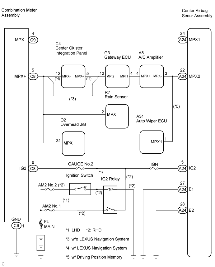

INSPECTION PROCEDURE
| 1. CHECK SRS WARNING LIGHT OPERATION |

Check the SRS warning light operation approximately 6 seconds after the ignition switch is turned to the ON position.
- Result:
SRS Warning Light Illumination
Proceed to
Remains on after it goes off
A
Remains on
B
|
|
||||

| A | |
 |
| 2. CHECK BATTERY |
Measure the voltage of the battery.
- Voltage:
- 11 to 14 V
|
|
||||

| OK | |
|
| 3. CHECK COMBINATION METER ASSEMBLY CONNECTOR |
Turn the ignition switch to the LOCK position.
Disconnect the connector from the combination meter assembly.
Check that the connector is not damaged.
- OK:
- The connector is not deformed or damaged.
|
|
||||
| OK | |
|
| 4. CHECK SOURCE VOLTAGE |
Connect the connector to the combination meter assembly.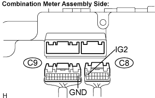
Measure the voltage and resistance according to the value (s) in the table below.
- Voltage and Resistance:
Tester connection
Condition
Specified condition
C8-8 (IG2) -
Body ground
Ignition switch ON
10 to 14 V
C9-1 (GND) -
Body ground
Always
Below 1 Ω
|
|
||||
| OK | |
|
| 5. PERFORM ACTIVE TEST BY INTELLIGENT TESTER (COMBINATION METER ASSEMBLY) |
Using the intelligent tester, perform the active test and check that the SRS warning light turns on and off.
- OK:
- The SRS warning light turns on and off in accordance with tester operation.
|
|
||||
| OK | ||
 |
||
| ||
| 6. CHECK BATTERY |
Measure the voltage of the battery.
- Voltage:
- 11 to 14 V
|
|
||||
| OK | |
|
| 7. CHECK CENTER AIRBAG SENSOR ASSEMBLY CONNECTOR |
Turn the ignition switch to the LOCK position.
Disconnect the negative (-) terminal cable from the battery, and wait for at least 90 seconds.
Disconnect the connector from the center airbag sensor assembly.
Check that the connector is not damaged.
- OK:
- The connector is not deformed or damaged.
|
|
||||
| OK | |
|
| 8. CHECK SOURCE VOLTAGE |
Connect the negative (-) terminal cable to the battery, and wait for at least 2 seconds.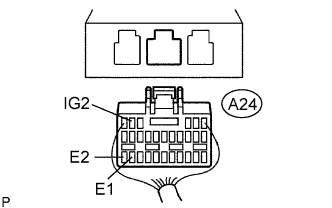
Turn the ignition switch to the ON position.
Measure the voltage and resistance according to the value (s) in the table below.
- Voltage and Resistance:
Tester connection
Condition
Specified condition
A24-5 (IG2) -
Body ground
Ignition switch ON
10 to 14 V
A24-27 (E1) -
Body ground
Always
Below 1 Ω
A24-28 (E2) -
Body ground
Always
Below 1 Ω
|
|
||||
| OK | |
|
| 9. PERFORM ACTIVE TEST BY INTELLIGENT TESTER (COMBINATION METER ASSEMBLY) |
Using the intelligent tester, perform the active test and check that the SRS warning light turns on and off.
- OK:
- The SRS warning light turns on and off in accordance with tester operation.
|
|
||||
| OK | ||
|
||
| ||