REMOVAL
Removal / installation
| 1. PRECAUTION |

| 2. REMOVE ENGINE ROOM SIDE LH COVER |
Using a clip remover, remove the engine room side cover.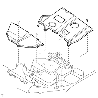

| 3. REMOVE ENGINE ROOM COVER SIDE |
Remove the 5 clips and engine room cover side.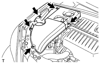
| 4. DISCHARGE FUEL SYSTEM PRESSURE |
| 5. REMOVE SERVICE PLUG GRIP |
- CAUTION:
- Remove the service plug to interrupt a high voltage circuit at the time of the check.
- Keep the removed service plug in your pocket to prevent other technicians from reconnecting it while you are servicing the vehicle.
- All the high voltage wiring connectors are colored in orange.
- Remove the service plug to interrupt a high voltage circuit at the time of the check.
Remove the 2 clips, then open the battery service hole cover.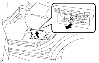
Wear insulation glove, and remove the service plug grip, after sliding up the lever of the service plug grip.
- CAUTION:
- Keep the removed service plug in your pocket to prevent other technicians from reconnecting it while you are servicing the vehicle.
- After removing the service plug grip, do not touch the high voltage connectors and terminals for 5 minutes.
- Keep the removed service plug in your pocket to prevent other technicians from reconnecting it while you are servicing the vehicle.
- NOTICE:
- After removing the service plug grip, do not operate the ignition switch as it may damage the hybrid vehicle control ECU.
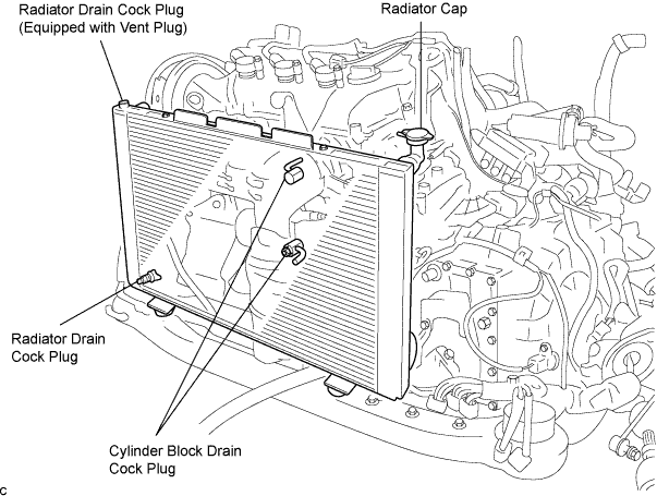
| 6. DRAIN COOLANT (Engine side) |
Remove the radiator cap.
- CAUTION:
- To avoid the danger of being burned, do not remove the radiator cap while the engine and radiator are still hot. Thermal expansion will cause hot engine coolant and steam to blow out from the radiator.
Drain the engine coolant by loosening the lower drain plug of the radiator and the cylinder block drain cock plugs.
- HINT:
- Engine coolant inside the radiator is drained from the drain hole located on the bottom of the engine under cover.
Tighten the cylinder block drain cock plugs.
- Torque:
- 13 N*m{ 133 kgf*cm , 9 in.*lbf }
| 7. DRAIN COOLANT (Hybrid side) |
Remove the transaxle side reserve tank.
- NOTICE:
- Do not remove the reserve tank cap when the engine is hot.
Loosen the bleeder plug shown in the illustration and drain the coolant.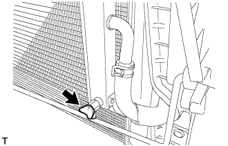
Close the bleeder plug.
Remove the plug and gasket shown in the illustration and drain the coolant.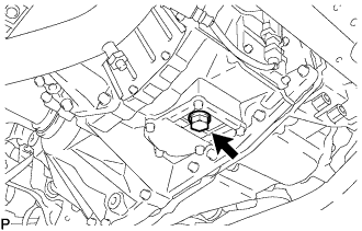
Install the plug with a new gasket.
- Torque:
- 39 N*m{ 398 kgf*cm , 29 ft.*lbf }
| 8. DRAIN ENGINE OIL |
Remove the oil filler cap.
Remove the oil drain plug, and drain the oil into a container.
Clean and install the oil drain plug with a new gasket.
- Torque:
- 45 N*m{ 459 kgf*cm , 33 ft.*lbf }
| 9. REMOVE FRONT WHEEL RH |
| 10. REMOVE ENGINE UNDER COVER NO.1 |
Remove the 6 bolts, 2 screws, 2 clips and engine under cover.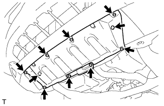
| 11. SEPARATE FRONT FENDER SPLASH SHIELD SUB-ASSEMBLY RH |
Remove the screw and separate the fender splash shield.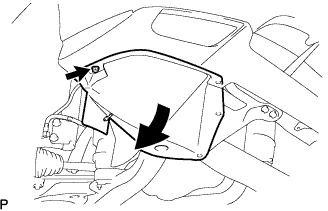
| 12. REMOVE FRONT FENDER APRON SEAL RH |
Remove the 2 bolts, clip and fender apron seal RH.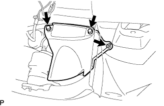
| 13. REMOVE ENGINE UNDER COVER NO.2 |
Remove the 2 bolts and engine under cover No.2.
| 14. REMOVE FRONT WIPER ARM AND BLADE ASSEMBLY RH |
Remove the 2 nuts and the front wiper arm and blade assembly RH.
| 15. REMOVE FRONT WIPER ARM AND BLADE ASSEMBLY LH |
Remove the nut and the front wiper arm and blade assembly LH.
| 16. REMOVE COWL TOP VENTILATOR LOUVER SUB-ASSEMBLY |
Remove the 2 clips.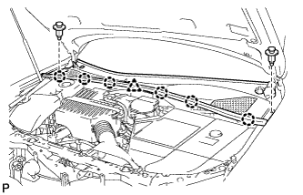
Disengage the 6 claws and the clamp, and remove the cowl top ventilator louver sub-assembly.
| 17. REMOVE WINDSHIELD WIPER MOTOR AND LINK ASSEMBLY |
Disconnect the connector.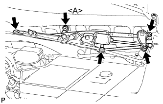
Remove the 5 bolts and the windshield wiper motor and link assembly.
- HINT:
- Bolt <A> cannot be removed because it is integrated into windshield wiper link assembly.
| 18. REMOVE COWL TOP PANEL SUB-ASSEMBLY OUTER |
Separate the wire harness clamp and grommet (A).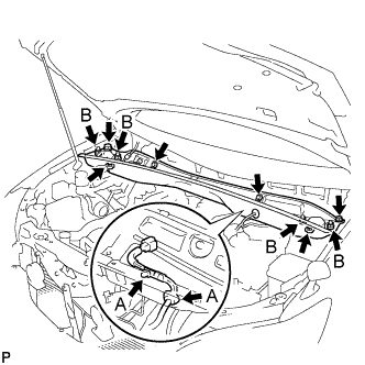
Remove the 4 shock absorber nuts (B).
Remove the 4 bolts, 2 nuts and cowl top panel sub-assembly.
Install the 4 shock absorber nuts.
- Torque:
- 80 N*m{ 815 kgf*cm , 59 ft.*lbf }
| 19. REMOVE BATTERY |
Remove the bolt and battery clamp.
Remove the battery and battery tray.
| 20. REMOVE BATTERY CARRIER SUB-ASSEMBLY |
Remove the 5 bolts and battery carrier.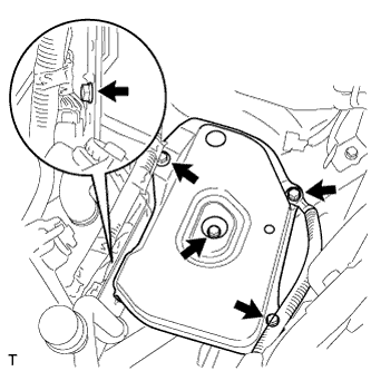
| 21. REMOVE COOL AIR INTAKE DUCT SEAL |
Remove the 4 clips and cool air intake duct seal.
| 22. REMOVE AIR CLEANER CAP W/ INLET |
Remove the 2 bolts, 4 clamps and air cleaner cap w/ inlet.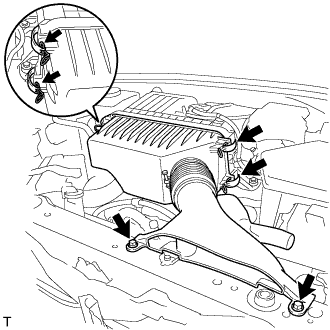
Remove the air cleaner filter element from the air cleaner case.
| 23. REMOVE AIR CLEANER CASE W/ RESONATOR |
Separate the ventilation hose No.2.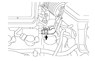
Disconnect the MAF meter connector.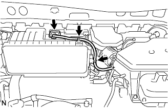
Disconnect the 2 wire harness clamps from the air cleaner.
Remove the 5 bolts from the air cleaner case w/ resonator.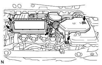
Remove the hose clamp, and separate the air cleaner hose No.1.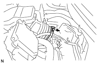
Remove the air cleaner case w/ resonator.
| 24. REMOVE W/ CONVERTER INVERTER ASSEMBLY |
| 25. REMOVE EMISSION CONTROL VALVE SET |
Disconnect the VSV connector (A).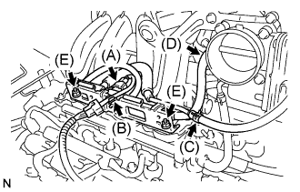
Remove the wire harness clamp (B).
Disconnect the fuel vapor feed hose No. 1 (C).
Disconnect the fuel vapor feed hose No. 2 (D).
Remove the 2 nuts (E), then remove the emission control valve set.
| 26. REMOVE INTAKE AIR SURGE TANK |
Disconnect the throttle motor connector (A).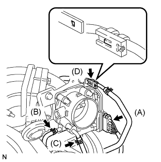
Separate the water by-pass hose No. 2 (B).
Separate the water by-pass hose No. 3 (C).
Separate the fuel vapor feed hose (D).
Disconnect the ventilation hose.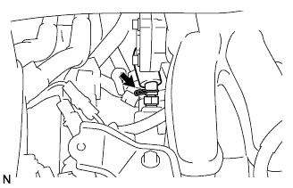
Remove the 2 bolts, then remove the engine hanger No.1 (A).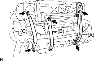
Remove the 2 bolts, then remove the surge tank stay No. 1 (B).
Remove the 2 bolts, then remove the surge tank stay No. 2 (C).
Disconnect the ground cable connector.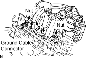
Using a socket hexagon wrench 8 mm, remove the 4 bolts.
Remove the 2 nuts, then remove the emission control valve bracket and the intake air surge tank.
Remove the gasket from the intake air surge tank.
| 27. DISCONNECT FUEL PIPE SUB-ASSEMBLY NO.1 |
Remove the EFI fuel pipe clamp.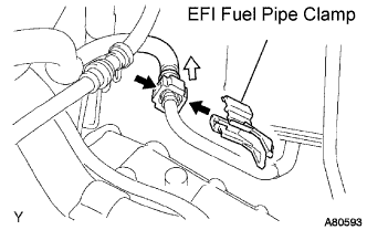
Pinch the retainer as illustrated, then pull out the fuel tube connector from the pipe.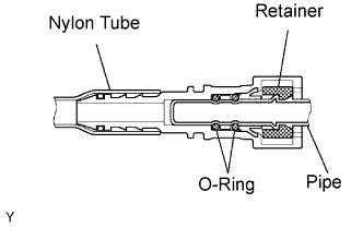
- NOTICE:
- Remove any dirt and foreign objects on the fuel tube connector before performing this work.
- Do not allow any scratches or foreign objects on the parts when disconnecting, as the fuel tube connector has the O-rings that seal the pipe.
- Perform this work by hand. Do not use any tools.
- Do not forcibly bend, twist or turn the nylon tube.
- Protect the disconnected part by covering it with a vinyl bag after disconnecting the fuel tube.
- If the fuel tube connector and pipe are stuck, push and pull them to release.
- Remove any dirt and foreign objects on the fuel tube connector before performing this work.
| 28. DISCONNECT HEATER INLET WATER HOSE |
Lock the hose clamp as shown in the illustration (A).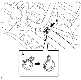
Disconnect the heater inlet water hose (B).
| 29. REMOVE INTAKE MANIFOLD |
Remove the nut and disconnect the ground cable (A).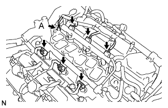
Disconnect the 6 fuel injector connectors.
In order to remove the intake manifold, using several steps, remove the 9 bolts and 2 nuts in the sequence shown in the illustration.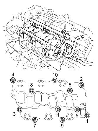
| 30. DISCONNECT RADIATOR HOSE INLET |
| 31. REMOVE WATER OUTLET |
Disconnect the ground cable connector (A).
Disconnect the engine coolant temperature sensor connector (B).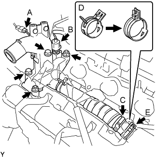
Remove the clamp (C).
Remove the 2 bolts, 2 nuts and 2 washers.
Lock the hose clamp as shown in the illustration (D) and remove the water outlet together with water by-pass hose No.1 (E).
Remove the 2 gaskets from the 2 cylinder heads.
| 32. SEPARATE BRAKE MASTER CYLINDER RESERVOIR SUB-ASSEMBLY |
Disconnect the connector.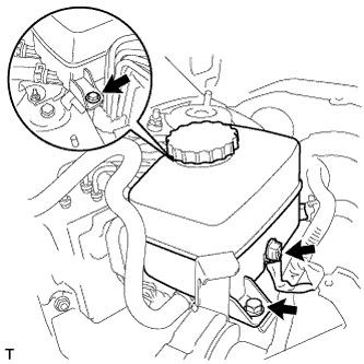
Remove the 2 bolts and separate the brake master cylinder reservoir.
| 33. REMOVE RESERVOIR BRACKET |
Disconnect the clamp.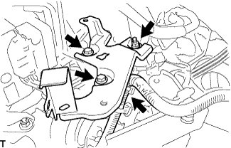
Remove the nut, 2 bolts and reservoir bracket.
| 34. REMOVE AIR CLEANER BRACKET |
Remove the 2 bolts and air cleaner bracket.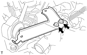
| 35. REMOVE ENGINE MOVING CONTROL ROD |
Remove the 4 bolts, the engine moving control rod and the bracket.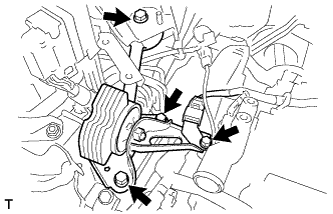
| 36. REMOVE ENGINE MOUNTING STAY NO.2 RH |
Remove the bolt, the engine mounting stay No.2 and the engine mounting bracket No.2.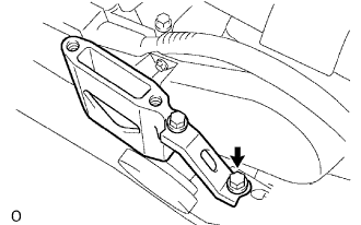
| 37. REMOVE CRANKSHAFT PULLEY |
Using SST, loosen the pulley bolt.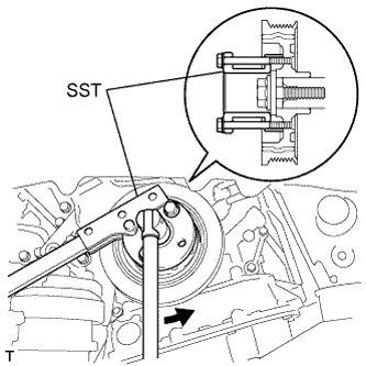
- SST
- 09213-54015
(91651-60855)
09330-00021
Using SST and the pulley bolt, remove the pulley.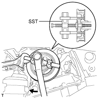
- SST
- 09950-50013
(09951-05010, 09952-05010, 09953-05020, 09954-05031)
- NOTICE:
- Before using SST, apply lubricating oil to the threads and tip of the center bolt 150.
| 38. REMOVE TIMING BELT NO.1 COVER |
Remove the 4 bolts and the timing belt cover No.1.
| 39. REMOVE TIMING BELT NO.2 COVER |
Disconnect the engine wire protector clamps from the timing belt No.2 cover.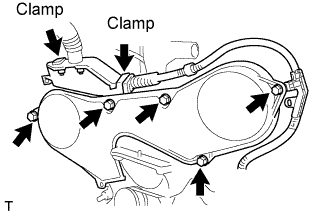
Remove the 5 bolts and the timing belt cover.
| 40. REMOVE ENGINE MOUNTING BRACKET RH |
Remove the 2 bolts, 2 nuts and engine mounting bracket RH.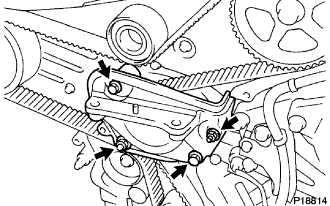
| 41. REMOVE TIMING BELT GUIDE NO.2 |
| 42. REMOVE TIMING BELT |
Set No.1 cylinder to TDC/compression.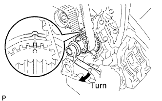
Temporarily install the crankshaft pulley bolt and washer to the crankshaft.
Turn the crankshaft clockwise, and align the timing mark of the crankshaft timing pulley with the oil pump body.
Check that the timing marks of the camshaft timing pulleys and No.3 timing belt cover are aligned.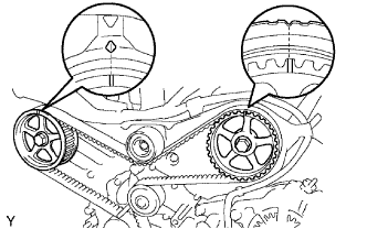
If not, turn the crankshaft 1 revolution (360°).Remove the crankshaft pulley bolt.
If reusing the timing belt, check that there are 3 installation marks on the timing belt as shown in the illustration.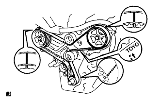
If the installation marks have disappeared, put new installation marks on the timing belt before removing.
Set No.1 cylinder to approximately 60° BTDC/compression.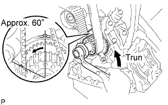
Turn the crankshaft counterclockwise by approximately 60°.
- NOTICE:
- If the timing belt is disengaged, having the crankshaft pulley at the wrong angle can cause the piston head and valve head to come into contact with each other when you remove the camshaft timing pulley and camshaft, causing damage. So always set the crankshaft pulley at the correct angle.
Remove the timing belt tensioner.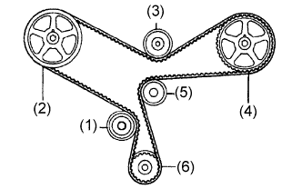
1st
No.1 idler pulley
2nd
RH camshaft timing pulley
3rd
No.2 idler pulley
4th
LH camshaft timing pulley
5th
Water pump pulley
6th
Crankshaft timing pulley
| 43. REMOVE TIMING BELT IDLER SUB-ASSEMBLY NO.2 |
Remove the bolt and timing belt idler sub-assembly No.2
| 44. REMOVE CAMSHAFT TIMING PULLEY |
Using SST, remove the bolt and the RH timing pulley.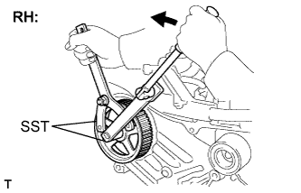
- SST
- 09960-10010
(09962-01000, 09963-01000)
09249-63010
Using SST, remove the bolt and the LH timing pulley.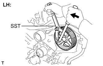
- SST
- 09960-10010
(09962-01000, 09963-01000)
- HINT:
- Arrange the camshaft timing pulleys (RH and LH sides) so that they can be returned to the original locations when reassembling.
| 45. REMOVE TIMING BELT NO.3 COVER |
Disconnect the 2 engine wire harness clamps from the timing belt No.3 cover.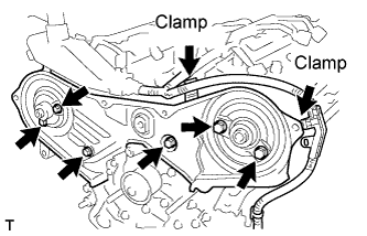
Remove the 6 bolts and the timing belt cover.
| 46. REMOVE EXHAUST PIPE ASSEMBLY FRONT |
Disconnect the heated oxygen sensor connector.
Remove the 2 bolts, 2 nuts and exhaust pipe assembly front.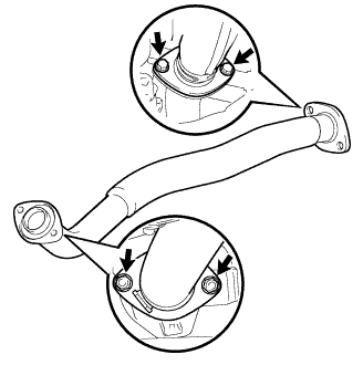
Remove the 2 gaskets.
| 47. REMOVE EXHAUST PIPE SUB-ASSEMBLY FRONT NO.3 |
Disconnect the heated oxygen sensor connector.
Remove the 2 bolts, 2 nuts and exhaust pipe sub-assembly front No.3.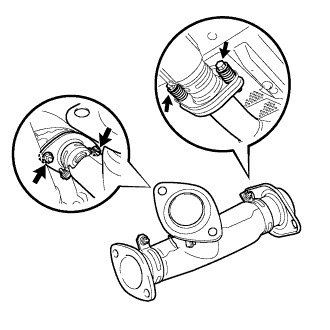
Remove the 2 gaskets.
| 48. REMOVE EXHAUST MANIFOLD HEAT INSULATOR NO.1 |
Remove the 3 bolts and exhaust manifold heat insulator No.1.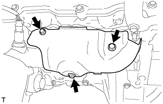
| 49. REMOVE MANIFOLD STAY |
Remove the 2 bolts and manifold stay.
| 50. REMOVE EXHAUST MANIFOLD SUB-ASSEMBLY RH |
Disconnect the heated oxygen sensor connector.
Using several steps, loosen and remove the 6 nuts in the sequence shown in the illustration.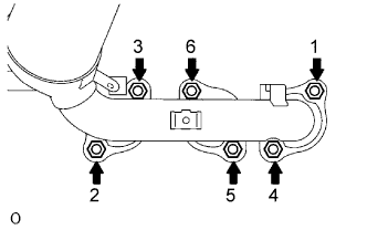
Remove the exhaust manifold RH and the gasket from the cylinder head RH.
| 51. REMOVE IGNITION COIL ASSEMBLY |
| 52. REMOVE CYLINDER HEAD COVER SUB-ASSEMBLY |
Remove the 2 engine wire harness clamps.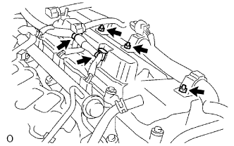
Remove the 3 nuts and disconnect the engine wire harness.
Remove the 9 bolts and the cylinder head cover.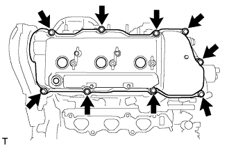
| 53. REMOVE CAMSHAFT |
- NOTICE:
- Since the thrust clearance of the camshaft is small, the camshaft must be kept level while it is being removed. If the camshaft is not kept level, damage to the cylinder head or to the camshaft may result. To avoid this, the following steps should be carried out.
Align the timing marks (2-dot mark) of the camshaft drive and the driven gears by turning the camshaft with a wrench.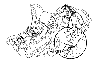
Secure the exhaust camshaft sub-gear to the main gear with a service bolt.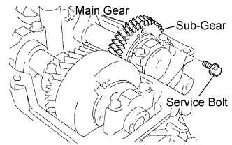
- Torque:
- 5.4 N*m{ 55 kgf*cm , 48 in.*lbf }
Recommended service bolt: Thread diameter
6 mm
Thread pitch
1.0 mm
Bolt length
16 to 20 mm
- HINT:
- When removing the camshaft, make certain that the torsional spring force of the sub-gear has been eliminated by installing the service bolt.
Using several steps, loosen and remove the 10 bearing cap bolts uniformly in the sequence shown in the illustration. Remove the 5 bearing caps and the camshaft.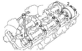
- NOTICE:
- Do not pry out the camshaft.
- Do not damage the portion of the cylinder head which receives the shaft thrust.
- Do not pry out the camshaft.
| 54. REMOVE NO.2 CAMSHAFT |
Using several steps, loosen and remove the 10 bearing cap bolts uniformly in the sequence shown in the illustration. Remove the 5 bearing caps and the No.2 camshaft.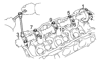
- NOTICE:
- Do not pry out the camshaft.
- Do not damage the portion of the cylinder head which receives the shaft thrust.
- Do not pry out the camshaft.
Remove the oil seal from the No.2 camshaft.
| 55. REMOVE CYLINDER HEAD SUB-ASSEMBLY |
Disconnect the VVT sensor connector.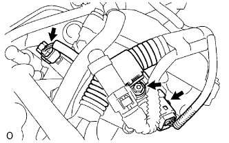
Disconnect the camshaft timing oil control valve connector.
Remove the nut and disconnect the engine wire harness clamp.
Using a socket hexagon wrench 8 mm, remove the hexagon bolt.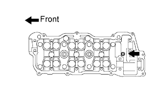
Using several steps, loosen the 8 cylinder head bolts uniformly in the sequence shown in the illustration. Remove the 8 cylinder head bolts and plate washers.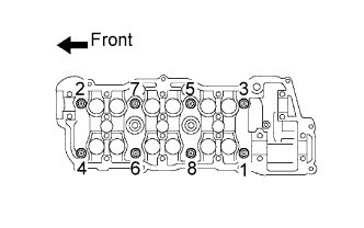
- SST
- 09011-38121
- NOTICE:
- Do not drop the washers into the cylinder head.
- Head warpage or cracking could result from removing bolts in an incorrect order.
- Do not drop the washers into the cylinder head.
| 56. REMOVE CYLINDER HEAD GASKET |
| 57. REMOVE MANIFOLD CONVERTER INSULATOR NO.3 |
Remove the bolt, nut and manifold converter insulator No.3.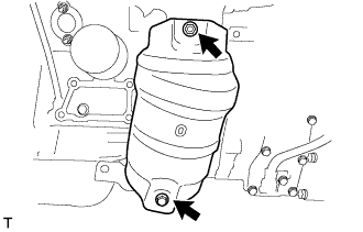
| 58. REMOVE EXHAUST MANIFOLD HEAT INSULATOR NO.2 |
Remove the 2 bolts and manifold heat insulator No.2.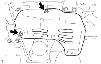
| 59. SEPARATE COOLING FAN ECU |
Remove the 2 bolts and separate the cooling fan ECU.
- HINT:
- The cooling fan ECU should be separated to prevent it from being interfered with by the exhaust manifold.
- Be sure to hang the disconnected ECU with the string to ensure safety.
- The cooling fan ECU should be separated to prevent it from being interfered with by the exhaust manifold.
| 60. REMOVE EXHAUST MANIFOLD CONVERTER SUB-ASSEMBLY NO.2 |
Disconnect the heated oxygen sensor connector.
Using several steps, loosen and remove the 6 nuts and bolt in the sequence shown in the illustration.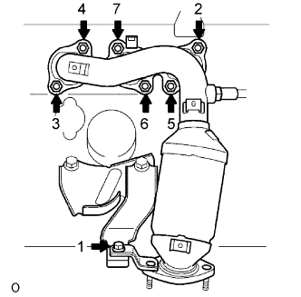
Remove the exhaust manifold converter No.2 and the gasket from the cylinder head LH.
| 61. REMOVE OIL LEVEL GAUGE GUIDE |
Remove the bolt which is used to secure the oil level gauge guide from the cylinder head LH.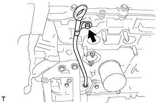
Pull out the oil level gauge guide and the oil level gauge together from the cylinder block.
Remove the O-ring from the oil level gauge guide.
| 62. REMOVE WATER INLET PIPE |
Remove the bolt and the water inlet pipe.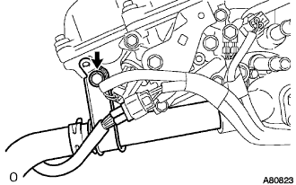
Remove the O-ring from the water inlet pipe.
| 63. REMOVE CYLINDER HEAD COVER SUB-ASSEMBLY LH |
Using an E6 "torx" socket wrench, remove the 2 bolts and disconnect the engine wire harness protector.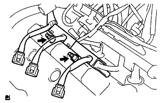
Remove the 2 engine wire harness clamps.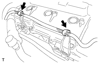
- CAUTION:
- Wear insulating gloves.
Remove the 2 bolts and 2 brackets.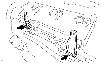
Remove the 9 bolts and the cylinder head cover.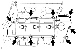
| 64. REMOVE NO.3 CAMSHAFT SUB-ASSEMBLY |
- NOTICE:
- Since the thrust clearance of the camshaft is small, the camshaft must be kept level while it is being removed. If the camshaft is not kept level, damage to the cylinder head or to the camshaft may result. To avoid this, the following steps should be carried out.
Align the timing marks (1-dot mark) of the camshaft drive and the driven gears by turning the camshaft with a wrench.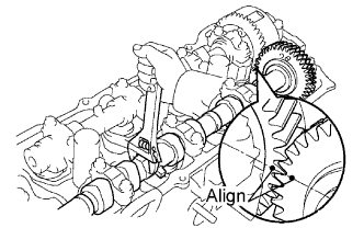
Secure the exhaust camshaft sub-gear to the main gear with a service bolt.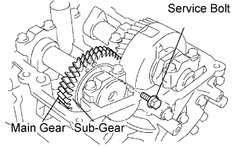
- Torque:
- 5.4 N*m{ 55 kgf*cm , 48 in.*lbf }
Recommended service bolt: Thread diameter
6 mm
Thread pitch
1.0 mm
Bolt length
16 to 20 mm
- HINT:
- When removing the camshaft, make certain that the torsional spring force of the sub-gear has been eliminated by installing the service bolt.
Using several steps, loosen and remove the 10 bearing cap bolts uniformly in the sequence shown in the illustration. Remove the 5 bearing caps and the No.3 camshaft.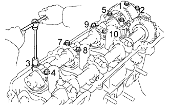
- NOTICE:
- Do not pry out the camshaft.
- Do not damage the portion of the cylinder head which receives the shaft thrust.
- Do not pry out the camshaft.
| 65. REMOVE NO.4 CAMSHAFT SUB-ASSEMBLY |
Using several steps, loosen and remove the 10 bearing cap bolts uniformly in the sequence shown in the illustration. Remove the 5 bearing caps and the No.4 camshaft.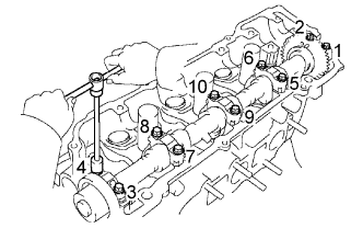
- NOTICE:
- Do not pry out the camshaft.
- Do not damage the portion of the cylinder head which receives the shaft thrust.
- Do not pry out the camshaft.
Remove the oil seal from the No.4 camshaft.
| 66. REMOVE CYLINDER HEAD LH |
Disconnect the VVT sensor connector (A).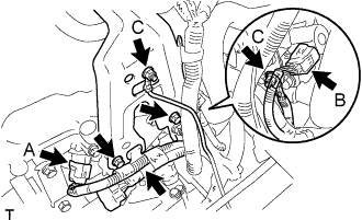
Disconnect the camshaft timing oil control valve connector (B).
Remove the 2 nuts and disconnect the ground cable (C).
Remove the 2 bolts, wire harness clamp and intake air connector bracket No.2.
Using a socket hexagon wrench 8 mm, remove the hexagon bolt.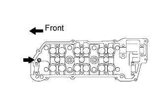
Using several steps, loosen the 8 cylinder head bolts uniformly in the sequence shown in the illustration. Remove the 8 cylinder head bolts and plate washers.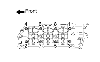
- SST
- 09011-38121
- NOTICE:
- Do not drop the washers into the cylinder head.
- Head warpage or cracking could result from removing bolts in an incorrect order.
- Do not drop the washers into the cylinder head.
| 67. REMOVE CYLINDER HEAD GASKET NO.2 |