Stereo Component Amplifier Power Source Circuit
Circuit diagnosis
DESCRIPTION
This circuit provides power to the stereo component amplifier.WIRING DIAGRAM
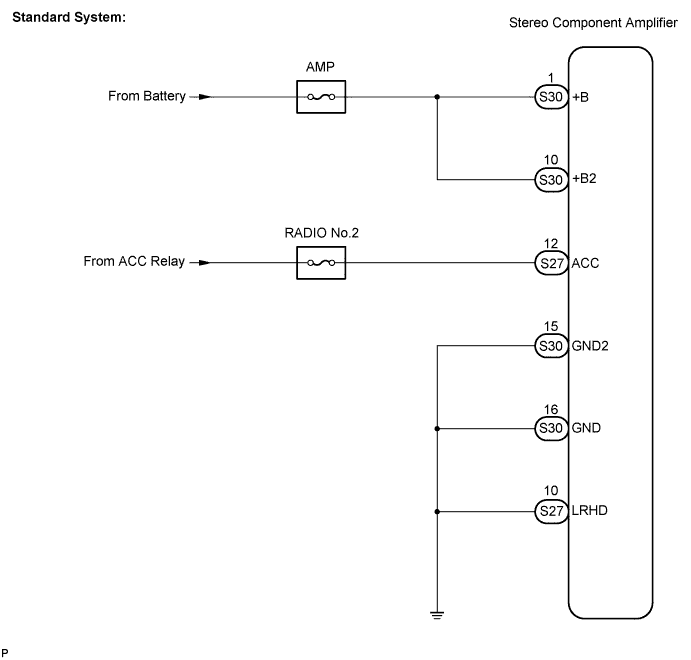

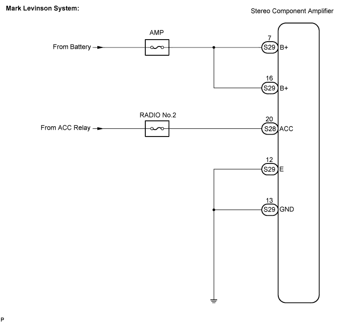
INSPECTION PROCEDURE
| 1. INSPECT STEREO COMPONENT AMPLIFIER |

Disconnect the stereo component amplifier connector.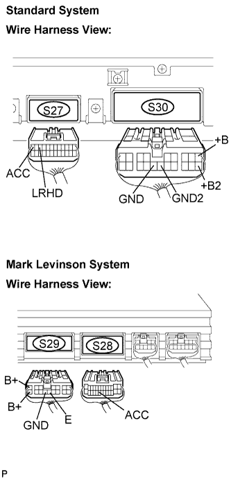
Measure the resistance according to the values in the table below.
- Standard resistance:
Tester connection
Condition
Specified condition
GND - Body ground
Always
Below 1 Ω
GND2/E - Body ground
Always
Below 1 Ω
LRHD - Body ground (*1)
Always
Below 1 Ω
Measure the voltage according to the values in the table below.
- Standard voltage:
Tester connection
Condition
Specified condition
B+ - GND
Always
10 to 14 V
+B - GND
Always
10 to 14 V
+B2 - GND
Always
10 to 14 V
ACC - GND
Ignition SW ACC
10 to 14 V
|
|
||||

| OK | ||
 |
||
| ||