TERMINALS OF ECU
System information
| INSTRUMENT PANEL JUNCTION BLOCK (MULTIPLEX NETWORK BODY ECU) |
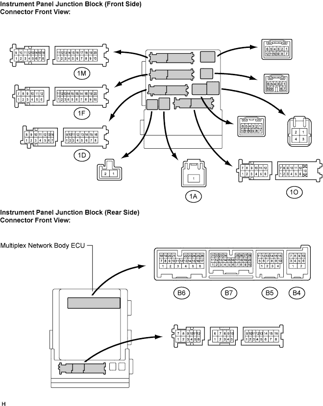

Disconnect the instrument panel J/B and multiplex network body ECU connectors.
Check the voltage or resistance according to the value(s) in the table below (wire harness side connector).
Symbols (Terminal No.)
Wiring Color
Terminal Description
Condition
Specified Condition
BATB (1A-1) - Body ground
B - Body ground
+B (power system, generator system) power supply
Always
10 to 14 V
BECU (1D-10) - Body ground
W - Body ground
+B (BECU) power supply
Always
10 to 14 V
ALTB (1D-16) - Body ground
W (LHD), R-Y (RHD) - Body ground
+B (power system, generator system) power supply
Always
10 to 14 V
GND1 (1F-10) - Body ground
W-B - Body ground
Ground
Always
Below 1 Ω
GND2 (1M-9) - Body ground
W-B - Body ground
Ground
Always
Below 1 Ω
LCTY (1O-7) - Body ground
B - Body ground
Rear courtesy light switch LH input
Rear door LH closed → opened
10 kΩ or higher → Below 1 Ω
DCTY (B5-14) - Body ground
L - Body ground
Driver side courtesy light switch input
Driver side door closed → opened
10 kΩ or higher → Below 1 Ω
RCTY (B5-16) - Body ground
GR - Body ground
Rear courtesy light switch RH input
Rear door RH closed → opened
10 kΩ or higher → Below 1 Ω
KSW (B6-21) - Body ground
B - Body ground
Unlock warning switch input
No key in ignition key cylinder → key inserted
10 kΩ or higher → Below 1 Ω
PCTY (B7-23) - Body ground
L - Body ground
Passenger side courtesy light switch input
Passenger side door closed → opened
10 kΩ or higher → Below 1 Ω
BCTY (B7-25) - Body ground
P - Body ground
Back door courtesy light switch input
Back door closed → opened
10 kΩ or higher → Below 1 Ω
- HINT:
- If the result is not as specified, there may be a malfunction on the wire harness side.
Reconnect the instrument panel J/B and multiplex network body ECU connectors.
Check the voltage according to the value(s) in the table below (ECU side connector).
If the result is not as specified, the instrument panel J/B (multiplex network body ECU) may have a malfunction.Symbols (Terminal No.)
Wiring Color
Terminal Description
Condition
Specified Condition
BZR (B4-2) - Body ground
W - Body ground
Wireless door lock buzzer
Wireless door lock buzzer OFF → ON
0 V → Pulse generation
HAZ (B6-2) - Body ground
Y - Body ground
Hazard warning light signal
Answer-back OFF → answer-back ON
10 to 14 V → Pulse generation
KSW (B6-21) - Body ground
B - Body ground
Unlock warning switch input
No key in the ignition key cylinder → key inserted
10 to 14 V → 0 V