Only Wireless Control Function is Inoperative
Circuit diagnosis
DESCRIPTION
The door control receiver receives a signal from the transmitter and sends this signal to the multiplex network body ECU. The multiplex network body ECU then controls operation of the door locks, power windows and sliding roof. The power back door ECU also causes the power back door to open or close when it receives a signal from the transmitter via the door control receiver and multiplex network body ECU.WIRING DIAGRAM
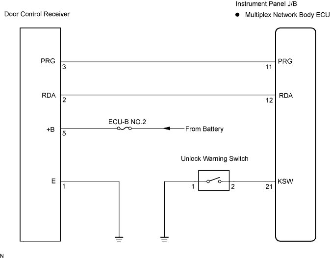

INSPECTION PROCEDURE
| 1. CHECK WIRELESS DOOR LOCK CONTROL FUNCTION |

Check the wireless door lock control system (Click here).
|
|
||||

| OK | ||
 |
||
| ||
| 2. CHECK DOOR CONTROL TRANSMITTER (LED) |
Check that the door control transmitter's LED comes on 3 times when the switch is pressed 3 times.
- OK:
- The door control transmitter's LED comes on 3 times when the switch is pressed 3 times.
|
|
||||
| OK | |
 |
| 3. CHECK WIRELESS DOOR LOCK CONTROL FUNCTION (NORMAL OPERATION) |
Check that UNLOCK-LOCK operates in normal operation.
- HINT:
- Standardized test procedure: Press the transmitter switch for 1 second, directing the beam to the driver's door outside handle from a distance of 1 m (3.28 ft). The transmitter should be pointed directly at the door handle, i.e. at 90° angle to the vehicle body.
|
|
||||

| OK | |
|
| 4. SWITCH TO SELF-DIAGNOSTIC MODE |
Switch to self-diagnostic mode using the intelligent tester.
Connect the intelligent tester to the DLC3.
Turn the ignition switch to the ON position and turn the intelligent tester main switch on.
- HINT:
- Refer to the intelligent tester operator's manual for further details.
Switch to self-diagnostic mode by performing the following:
Put the vehicle under the initial condition (Click here).
Insert the key into the ignition key cylinder and remove it.
Within 5 seconds after the key is removed, insert the key into the ignition key cylinder.
Turn the ignition switch to the ON position and turn it back to the LOCK position.
Within 30 seconds of turning the ignition switch off again, perform the following 9 times: Turn the ignition switch to the ON position and turn it back to the LOCK position.
- HINT:
- Turning the ignition switch to the ON position after step 5 has been completed will end the self-diagnostic mode.
- Do not lock or unlock doors during the self-diagnostic mode.
- Turning the ignition switch to the ON position after step 5 has been completed will end the self-diagnostic mode.
- NOTICE:
- If the self-diagnostic mode cannot be achieved, the system will return to normal mode.
Check that the system has switched to self-diagnostic mode by checking the sound of the wireless door lock buzzer.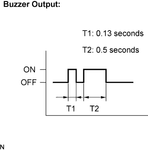
- OK:
- The sound pattern of the wireless door lock buzzer should be the same as the patterns shown in the timing chart on the left.
|
|
||||
| OK | |
|
| 5. CHECK BY SELF-DIAGNOSTIC MODE |
Check the diagnostic outputs when the door control transmitter switch is held down. The diagnostic outputs can be checked by the sound of the wireless door lock buzzer.
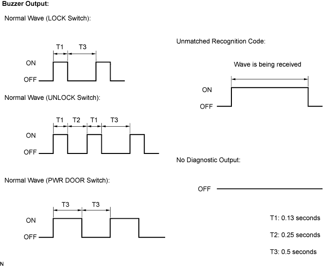
- Result:
Condition
Proceed to
Unmatched recognition code is output
A
Normal waves patterns from the wireless door lock buzzer are output for LOCK, UNLOCK and PWR DOOR
B
No diagnostic outputs are recorded
C
|
|
||||
|
|
||||
| A | |
|
| 6. REGISTER RECOGNITION CODE |
Check that the system can switch to the rewrite mode or add mode and whether a recognition code can be registered.
- OK:
- The system can switch to the rewrite mode or add mode, and a recognition code can be registered.
|
|
||||
| OK | ||
|
||
| ||
| 7. CHECK TRANSMITTER BATTERY |
Replace the existing battery with a new or normally functioning one and check that the transmitter LED comes on 3 times when the switch is pressed 3 times.
|
|
||||
| OK | ||
|
||
| ||
| 8. CHECK RESPONSE OF DOOR CONTROL RECEIVER |
Press and hold down any switch on a new or normal door control transmitter for the same vehicle type and check that an unmatched recognition code is output.
- OK:
- Unmatched recognition code is output.
|
|
||||
| OK | ||
|
||
| ||
| 9. CONFIRM INPUT METHOD FOR SELF-DIAGNOSTIC MODE |
Confirm input method for self-diagnostic mode.
- Result:
Condition
Proceed to
Method for changing system self-diagnostic mode works
A
Method for changing system self-diagnostic mode does not work
B
|
|
||||
| A | |
|
| 10. READ VALUE OF INTELLIGENT TESTER (UNLOCK WARNING SWITCH) |
Connect the intelligent tester to the DLC3.
Turn the ignition switch to the ON position and turn the intelligent tester main switch on.
Select the item below in the DATA LIST and read the display on the intelligent tester.
Body: Item (Display)
Measurement Item / Display (Range)
Normal Condition
Diagnostic Note
Key Unlock Warning SW
Unlock warning switch / ON or OFF
ON: Ignition key is inserted
OFF: Ignition key is not inserted
-
- OK:
- When the ignition key is operated, the display changes as shown above.
|
|
||||
| NG | |
|
| 11. INSPECT UNLOCK WARNING SWITCH |
Disconnect the unlock warning switch connector.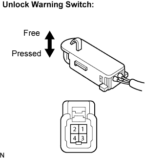
Measure the resistance according to the value(s) in the table below.
- Standard resistance:
Tester Connection
Condition
Specified Condition
1 - 2
Switch pressed (Key set)
Below 1 Ω
1 - 2
Switch free (Key removed)
10 kΩ or higher
|
|
||||
| OK | |
|
| 12. CHECK HARNESS AND CONNECTOR (MULTIPLEX NETWORK BODY ECU TO UNLOCK WARNING SWITCH) |
Disconnect the multiplex network body ECU (B6) connector.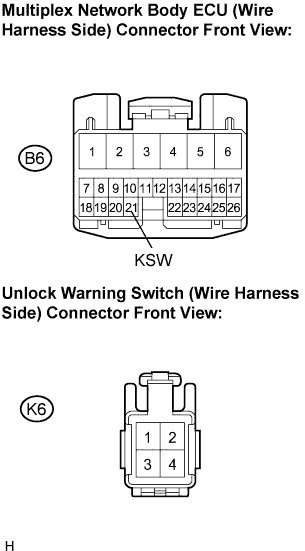
Measure the resistance according to the value(s) in the table below.
- Standard resistance:
Tester Connection
Condition
Specified Condition
B6-21 (KSW) - K6-2
Always
Below 1 Ω
B6-21 (KSW) - Body ground
Always
10 kΩ or higher
K6-1 - Body ground
Always
Below 1 Ω
|
|
||||
| OK | |
|
| 13. INSPECT DOOR CONTROL RECEIVER (+B TERMINAL) |
Disconnect the door control receiver connector.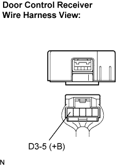
Measure the voltage according to the value(s) in the table below.
- Standard voltage:
Tester Connection
Condition
Specified Condition
D3-5 (+B) - Body ground
Always
10 to 14 V
|
|
||||
| OK | |
|
| 14. INSPECT DOOR CONTROL RECEIVER (E TERMINAL) |
Measure the resistance according to the value(s) in the table below.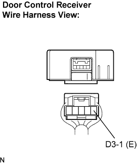
- Standard resistance:
Tester Connection
Condition
Specified Condition
D3-1 (E) - Body ground
Always
Below 1 Ω
|
|
||||
| OK | |
|
| 15. CHECK HARNESS AND CONNECTOR (MULTIPLEX NETWORK BODY ECU TO DOOR CONTROL RECEIVER) |
Disconnect the multiplex network body ECU (B5) connector.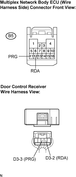
Measure the resistance according to the value(s) in the table below.
- Standard resistance:
Tester Connection
Condition
Specified Condition
B5-11 (PRG) - D3-3 (PRG)
Always
Below 1 Ω
B5-11 (PRG) - Body ground
Always
10 kΩ or higher
B5-12 (RDA) - D3-2 (RDA)
Always
Below 1 Ω
B5-12 (RDA) - Body ground
Always
10 kΩ or higher
|
|
||||
| OK | |
|
| 16. REPLACE DOOR CONTROL RECEIVER WITH NORMAL ONE |
- OK:
- The system returns to normal operation.
|
|
||||
| OK | ||
|
||
| ||