REMOVAL
Removal / installation
| 1. REMOVE ENGINE ROOM SIDE LH COVER |

Using a clip remover, remove the engine room side cover.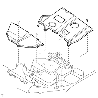

| 2. REMOVE ENGINE ROOM COVER SIDE |
Remove the 5 clips and engine room cover side.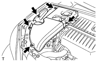
| 3. DISCONNECT CABLE FROM NEGATIVE BATTERY TERMINAL |
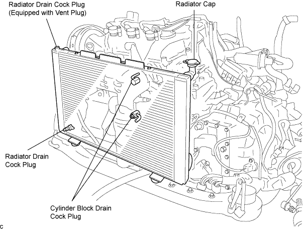
| 4. DRAIN COOLANT |
Remove the radiator cap.
- CAUTION:
- To avoid the danger of being burned, do not remove the radiator cap while the engine and radiator are still hot. Thermal expansion will cause hot engine coolant and steam to blow out from the radiator.
Drain the engine coolant by loosening the lower drain plug of the radiator and the cylinder block drain cock plugs.
- HINT:
- Engine coolant inside the radiator is drained from the drain hole located on the bottom of the engine under cover.
Tighten the cylinder block drain cock plugs.
- Torque:
- 13 N*m{ 133 kgf*cm , 9 in.*lbf }
| 5. REMOVE FRONT WIPER ARM AND BLADE ASSEMBLY RH |
Remove the 2 nuts and the front wiper arm and blade assembly RH.
| 6. REMOVE FRONT WIPER ARM AND BLADE ASSEMBLY LH |
Remove the nut and the front wiper arm and blade assembly LH.
| 7. REMOVE COWL TOP VENTILATOR LOUVER SUB-ASSEMBLY |
Remove the 2 clips.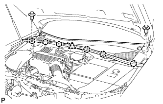
Disengage the 6 claws and the clamp, and remove the cowl top ventilator louver sub-assembly.
| 8. REMOVE WINDSHIELD WIPER MOTOR AND LINK ASSEMBLY |
Disconnect the connector.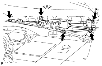
Remove the 5 bolts and the windshield wiper motor and link assembly.
- HINT:
- Bolt <A> cannot be removed because it is integrated into windshield wiper link assembly.
| 9. REMOVE COWL TOP PANEL SUB-ASSEMBLY OUTER |
Separate the wire harness clamp and grommet (A).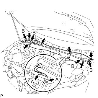
Remove the 4 shock absorber nuts (B).
Remove the 4 bolts, 2 nuts and cowl top panel sub-assembly.
Install the 4 shock absorber nuts.
- Torque:
- 80 N*m{ 815 kgf*cm , 59 ft.*lbf }
| 10. REMOVE COOL AIR INTAKE DUCT SEAL |
Remove the 4 clips and cool air intake duct seal.
| 11. REMOVE AIR CLEANER CAP W/ INLET |
Disconnect the 4 clamps.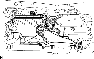
Remove the 2 bolts and air cleaner cap w/ inlet.
Remove the air cleaner element from the air cleaner case.
| 12. REMOVE AIR CLEANER CASE W/ RESONATOR |
Separate the ventilation hose No.2.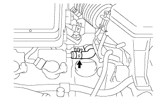
Disconnect the MAF meter connector.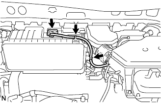
Disconnect the 2 wire harness clamps from the air cleaner.
Remove the 5 bolts from the air cleaner case w/ resonator.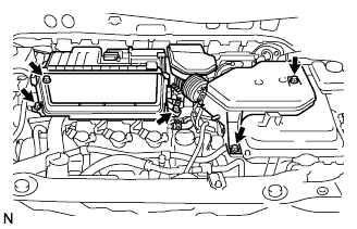
Remove the hose clamp, and separate the air cleaner hose No.1.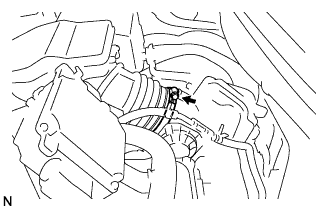
Remove the air cleaner case w/ resonator.
| 13. REMOVE THROTTLE BODY ASSEMBLY |
Disconnect the throttle motor connector (A).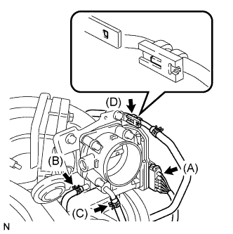
Separate the water by-pass hose No.2 (B).
Separate the water by-pass hose No.3 (C).
Separate the fuel vapor feed hose (D).
Remove the 4 bolts and the throttle body assembly.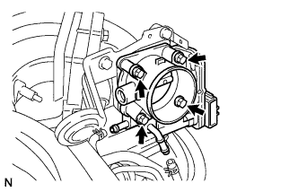
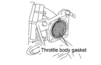
Remove the throttle body gasket from the intake air connector.