Power Seat Motor Circuit
Circuit diagnosis
DESCRIPTION
When the power seat control switch is operated, a command signal is sent to the position control ECU and switch assembly (power seat control switch and ECU). The front power seat switch then controls the appropriate seat motor as needed. This memory system does not use a seat position sensor. The seat position is detected by counting pulses that are output when the motor turns. If there is no pulse output from the motor, the motor will stop operating. The position control ECU and switch assembly (power seat control switch and ECU) is designed so that any malfunction of the seat memory system will not interfere with manual seat control.If the position control ECU and switch assembly (power seat control switch and ECU) detects a low motor speed, abnormal activity, or sudden motor current fluctuation, the system will stop the motor. If the motor operates continuously for 120 seconds or more, the system will stop the motor until the switch is turned on again.
WIRING DIAGRAM
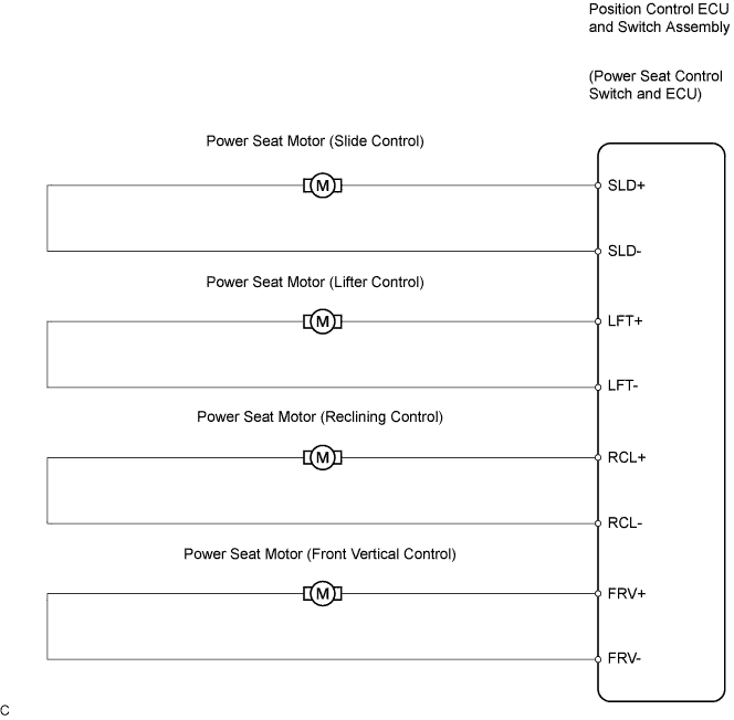

INSPECTION PROCEDURE
| 1. PERFORM ACTIVE TEST BY INTELLIGENT TESTER |

Connect the intelligent tester to the DLC3.
Turn the ignition switch on.
Perform the ACTIVE TEST by following the directions on the tester screen.
D_SEAT (Position control ECU and switch assembly) Item
Test Details
Diagnostic Note
Seat Reclining
Test detail: reclining operation FRONT/REAR
Vehicle condition: stopped
-
Front Vertical Operation
Test detail: front vertical operation UP/DOWN
Vehicle condition: stopped
-
Lifter Operation
Test detail: lifter operation UP/DOWN
Vehicle condition: stopped
-
Seat Slide Operation
Test detail: sliding operation UP/DOWN
Vehicle condition: stopped
-
- OK:
- Each power seat motor operates.
|
|
||||

| OK | ||
 |
||
| ||
| 2. INSPECT FRONT SEAT ADJUSTER SUB-ASSEMBLY (POWER SEAT MOTOR) |
Inspect the power seat motor (Click here).
- OK:
- The power seat motor operates.
|
|
||||

| OK | |
 |
| 3. CHECK HARNESS AND CONNECTOR (POSITION CONTROL ECU AND SWITCH ASSEMBLY - POWER SEAT MOTOR) |
Disconnect the position control ECU and switch assembly connector and power seat motor connectors.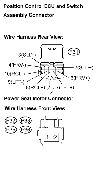
Measure the resistance according to the value(s) in the table below.
- Resistance:
- LHD:
Tester Connection
Condition
Specified Condition
P31-2(SLD+) - P36-1
Always
Below 1 Ω
P31-3(SLD-) - P36-2
Always
Below 1 Ω
P31-4(FRV-) - P32-2
Always
Below 1 Ω
P31-6(FRV+) - P32-1
Always
Below 1 Ω
P31-7(LFT+) - P33-2
Always
Below 1 Ω
P31-9(LFT-) - P33-1
Always
Below 1 Ω
P31-8(RCL+) - P35-2
Always
Below 1 Ω
P31-10(RCL-) - P35-1
Always
Below 1 Ω
P31-2(SLD+) - Body ground
Always
10 kΩ or higher
P31-3(SLD-) - Body ground
Always
10 kΩ or higher
P31-4(FRV-) - Body ground
Always
10 kΩ or higher
P31-6(FRV+) - Body ground
Always
10 kΩ or higher
P31-7(LFT+) - Body ground
Always
10 kΩ or higher
P31-9(LFT-) - Body ground
Always
10 kΩ or higher
P31-8(RCL+) - Body ground
Always
10 kΩ or higher
P31-10(RCL-) - Body ground
Always
10 kΩ or higher
- RHD:
Tester Connection
Condition
Specified Condition
P31-2(SLD+) - P36-2
Always
Below 1 Ω
P31-3(SLD-) - P36-1
Always
Below 1 Ω
P31-4(FRV-) - P32-1
Always
Below 1 Ω
P31-6(FRV+) - P32-2
Always
Below 1 Ω
P31-7(LFT+) - P33-1
Always
Below 1 Ω
P31-9(LFT-) - P33-2
Always
Below 1 Ω
P31-8(RCL+) - P35-2
Always
Below 1 Ω
P31-10(RCL-) - P35-1
Always
Below 1 Ω
P31-2(SLD+) - Body ground
Always
10 kΩ or higher
P31-3(SLD-) - Body ground
Always
10 kΩ or higher
P31-4(FRV-) - Body ground
Always
10 kΩ or higher
P31-6(FRV+) - Body ground
Always
10 kΩ or higher
P31-7(LFT+) - Body ground
Always
10 kΩ or higher
P31-9(LFT-) - Body ground
Always
10 kΩ or higher
P31-8(RCL+) - Body ground
Always
10 kΩ or higher
P31-10(RCL-) - Body ground
Always
10 kΩ or higher
|
|
||||
| OK | ||
|
||
| ||