Inside Handle Illumination Light Circuit
Circuit diagnosis
DESCRIPTION
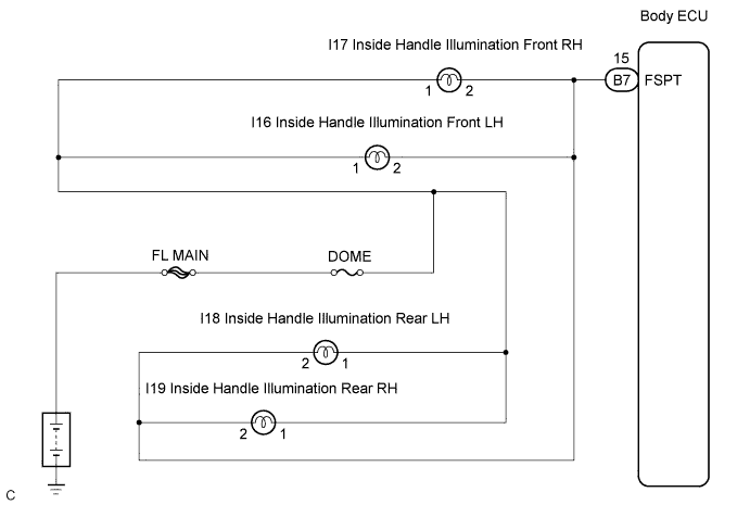
The body ECU receives information regarding the door lock position switch and ignition switch, and turns on each inside handle illumination. It also receives shift position information and controls the illumination.WIRING DIAGRAM

INSPECTION PROCEDURE
| 1. PERFORM ACTIVE TEST BY INTELLIGENT TESTER |

Connect the intelligent tester to the DLC3.
Turn the ignition switch to the ON position and press the intelligent tester main switch ON.
Select the items below in the ACTIVE TEST, and then check that the relay operates.
BODY NO.1 Item
Test Details
Diagnostic Note
Step Light Operation
Inside handle illumination ON/OFF
-
|
|
||||

| OK | ||
 |
||
| ||
| 2. INSPECT INTERIOR LIGHT |
Inspect each inside handle illumination (Click here).
|
|
||||

| OK | |
 |
| 3. INSPECT INSTRUMENT PANEL JUNCTION BLOCK ASSEMBLY |
Measure the voltage according to the value(s) in the table below.
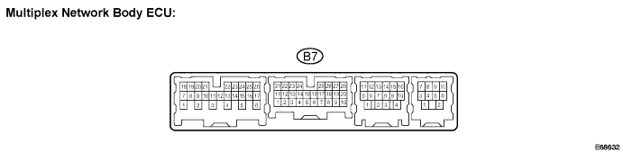
- Voltage:
Tester connection
Condition
Specified condition
B7-15 - Body ground
All door is closed → Front or rear door is open
10 to 14 V → Below 1 V
|
|
||||
| OK | ||
|
||
| ||