DISASSEMBLY
Removal / installation
| 1. REMOVE TRANSPONDER KEY AMPLIFIER |

Using a screwdriver, widen the claws hanging onto the steering column upper bracket by approximately 1.0 mm (0.039 in.).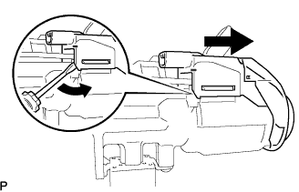

Pull out the transponder key amplifier with the claw open.
- NOTICE:
- Using excessive force may damage the case.
| 2. REMOVE STEERING COLUMN UPPER WITH SWITCH BRACKET ASSEMBLY |
Using a center punch, mark the center of the 2 tapered-head bolts.
Using a 3 to 4 mm (0.12 to 0.16 in.) drill, drill a hole in the 2 tapered-head bolts.
Using a screw extractor, remove the 2 tapered-head bolts and steering column upper with switch bracket assembly from the steering column assembly.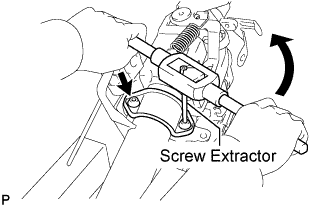
| 3. REMOVE IGNITION SWITCH LOCK CYLINDER ASSEMBLY |
Put the ignition switch lock cylinder assembly in the ACC position.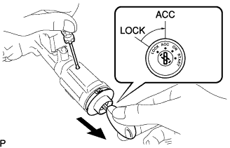
Push down the stop pin with a screwdriver, and pull out the ignition switch lock cylinder assembly.
| 4. REMOVE UN-LOCK WARNING SWITCH ASSEMBLY |
Separate the un-lock warning switch assembly connector from the ignition or starter switch assembly.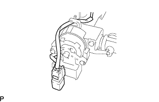
Remove the un-lock warning switch assembly by pushing up the center part and releasing the 2 claws.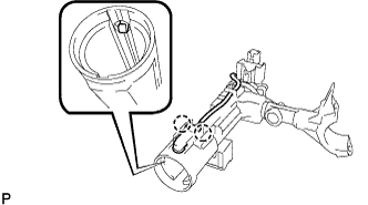
Disengage the secondary locking device of the un-lock warning switch assembly connector.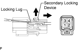
Using a screwdriver, disengage the locking lug of terminals 3 and 4, and pull the terminals out from the rear side of the un-lock warning switch assembly connector.
| 5. REMOVE KEY INTER LOCK SOLENOID |
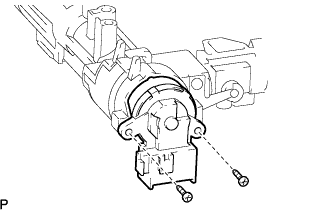
Remove the 2 screws and key inter lock solenoid from the steering column upper with switch bracket assembly.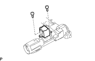
| 6. REMOVE IGNITION OR STARTER SWITCH ASSEMBLY |
Remove the 2 screws and ignition or starter switch assembly from the steering column upper with switch bracket assembly.