INSTALLATION
Removal / installation
| 1. INSTALL AMPLIFIER ANTENNA |

Set the amplifier antenna into the hole on the roof, and place the amplifier antenna cord in the cutout on the amplifier antenna.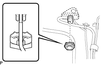

Install the amplifier antenna with the antenna nut.
- Torque:
- 4.5 N*m{ 46 kgf*cm , 40 in.*lbf }
Engage the 3 clamps and connect the 2 connectors.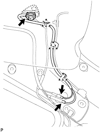
| 2. INSTALL RADIO ANTENNA POLE |
Install the radio antenna pole turning it in the direction of the arrow shown in the illustration.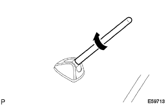
| 3. INSTALL ROOF HEADLINING ASSEMBLY |
Place the roof headlining to the vehicle from the back door side.
Engage the 2 fasteners and 3 clips. (w/o sliding roof)
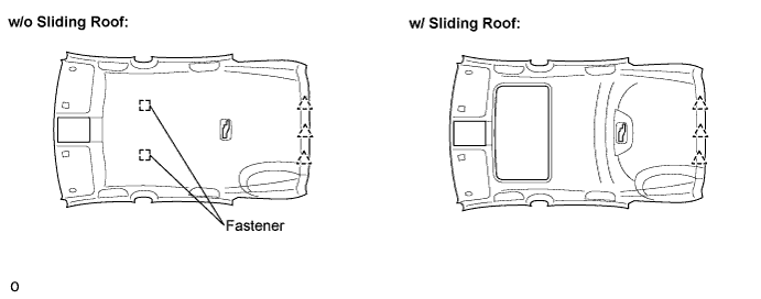
Engage the 3 clips. (w/ sliding roof)
Install the sunroof opening trim moulding. (w/ sliding roof)
Connect the sliding roof drive gear connector. (w/ sliding roof)
Connect the washer hose. Connect the radio antenna cord connector and engage the clamps to the rear quarter pillar RH.
Connect the roof wire connector and engage the clamps to the front pillar LH.
Connect the washer hose. Connect the radio antenna cord connector and engage the clamps to the front pillar RH.
Install the radio antenna cord connector bolt to the front pillar RH.
| 4. INSTALL VISOR HOLDER |
| 5. INSTALL LH VISOR ASSEMBLY |
Connect the connector.
Install the visor assembly with the 2 screws.
Engage the 4 claws and install the visor bracket cover.
| 6. INSTALL RH VISOR ASSEMBLY |
| 7. INSTALL MAP LIGHT ASSEMBLY |
Connect the connector.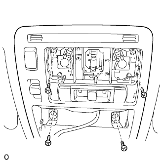
Install the map light with the 4 screws.
Engage the claws and install the 2 caps.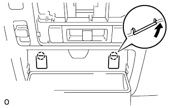
w/o sliding roof: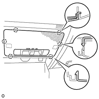
Engage the 6 claws and install the lens cover.
w/ sliding roof: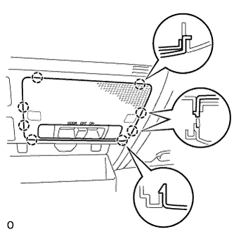
Engage the 8 claws and install the lens cover.
| 8. INSTALL NO.1 ROOM LIGHT ASSEMBLY |
Connect the connector.
Engage the 2 claws and 2 springs, and install the room light assembly No.1.
Engage the 4 claws and install the lens cover.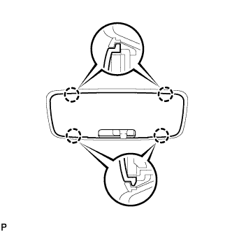
| 9. INSTALL RAIN SENSOR (w/ rain sensor) |
Connect the connector.
Install the rain sensor.
- NOTICE:
- If there is any residue left from the silicon sheet on the windshield, remove it.
- Clean the dirt on the glass with a cloth etc.
- When installing a new rain sensor, peel the release paper off from the silicon sheet first.
- Be careful not to leave any air bubbles in the rain sensor when installing it.
- If there is any residue left from the silicon sheet on the windshield, remove it.
| 10. INSTALL ASSIST GRIP SUB-ASSEMBLY |
Install the assist grip sub-assembly with the 2 screws.
Engage the 6 claws and install the 2 assist grip covers.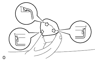
- HINT:
- Use the same procedure for the other 3 assist grips.
| 11. INSTALL ROOF SIDE GARNISH ASSEMBLY INNER LH |
Engage the 7 clips and install the roof side garnish assembly inner.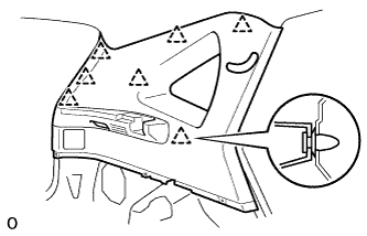
Install the 3 clips.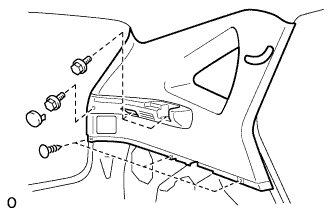
Install the 3 bolts and tonneau cover holder cap.
Engage the 4 claws and install the seat belt bezel.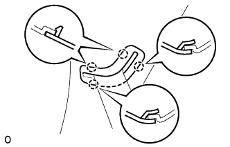
| 12. INSTALL ROOF SIDE GARNISH ASSEMBLY INNER RH |
| 13. INSTALL NO.1 TONNEAU COVER HOLDER CAP |
| 14. INSTALL NO.2 ROOM LIGHT ASSEMBLY |
Connect the connector.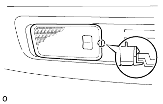
Engage the claw and install the room light assembly No.2.
| 15. INSTALL DECK TRIM SIDE PANEL ASSEMBLY LH |
Engage the 2 clips and install the deck trim side panel assembly.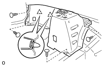
Install the 4 clips.
| 16. INSTALL DECK TRIM SIDE PANEL ASSEMBLY RH |
| 17. INSTALL ROPE HOOK |
Install the 2 rope hooks with the 2 bolts.
- Torque:
- 8.0 N*m{ 80 kgf*cm , 71 in.*lbf }
- HINT:
- Use the same procedure to install the other side.
| 18. INSTALL REAR FLOOR FINISH SIDE PLATE LH |
Engage the 2 clips and install the rear floor finish side plate.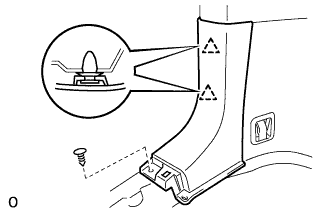
Install the clip.
| 19. INSTALL REAR FLOOR FINISH SIDE PLATE RH |
| 20. INSTALL REAR SEAT SIDE COVER LH |
Engage the 4 clips and install the rear seat side cover.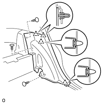
Install the 3 clips.
| 21. INSTALL REAR SEAT SIDE COVER RH |
| 22. INSTALL REAR NO.1 SEAT BELT ASSEMBLY OUTER LH |
Install the rear No.1 seat outer belt assembly with the bolt.
- Torque:
- 42 N*m{ 428 kgf*cm , 31 ft.*lbf }
| 23. INSTALL REAR NO.1 SEAT BELT ASSEMBLY OUTER RH |
| 24. INSTALL DECK SIDE TRIM COVER LH |
Engage the 5 claws and install the deck side trim cover.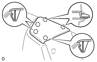
| 25. INSTALL DECK SIDE TRIM COVER RH |
| 26. INSTALL CENTER PILLAR GARNISH LH |
Engage the clip and install the center pillar garnish.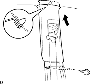
Install the 2 screws.
| 27. INSTALL CENTER PILLAR GARNISH RH |
| 28. INSTALL CENTER PILLAR GARNISH LOWER LH |
Engage the 2 clips and 3 claws, install the center pillar garnish lower.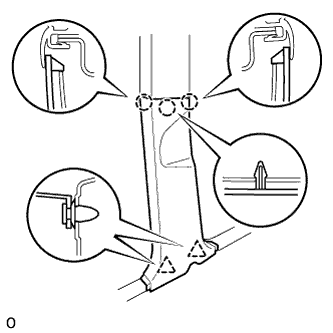
| 29. INSTALL CENTER PILLAR GARNISH LOWER RH |
| 30. INSTALL FRONT SEAT OUTER BELT ASSEMBLY LH |
Install the front seat outer belt assembly with the bolt.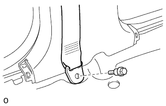
- Torque:
- 42 N*m{ 428 kgf*cm , 31 ft.*lbf }
| 31. INSTALL FRONT SEAT OUTER BELT ASSEMBLY RH |
| 32. INSTALL LAP BELT OUTER ANCHOR COVER |
Engage the 2 claws and install the lap belt outer anchor cover as shown in the illustration.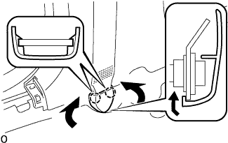
- HINT:
- Use the same procedure to install the other side.
| 33. INSTALL FRONT PILLAR GARNISH LH |
Install a new clip (A) on the front pillar garnish.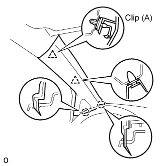
Engage the 2 claws and 2 clips, and install the front pillar garnish.
| 34. INSTALL FRONT PILLAR GARNISH RH |
| 35. INSTALL REAR DOOR OPENING TRIM WEATHERSTRIP LH |
| 36. INSTALL REAR DOOR OPENING TRIM WEATHERSTRIP RH |
| 37. INSTALL REAR DOOR SCUFF PLATE LH |
Connect the connector. (w/ illumination scuff plate)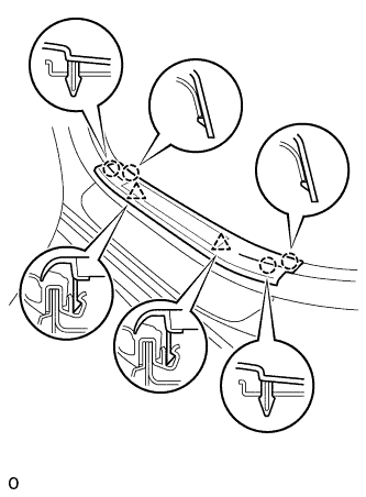
Engage the 4 claws and 2 clips, and install the rear door scuff plate.
| 38. INSTALL REAR DOOR SCUFF PLATE RH |
| 39. INSTALL FRONT DOOR OPENING TRIM WEATHERSTRIP LH |
| 40. INSTALL FRONT DOOR OPENING TRIM WEATHERSTRIP RH |
| 41. INSTALL FRONT DOOR SCUFF PLATE LH |
Connect the connector. (w/ illumination scuff plate)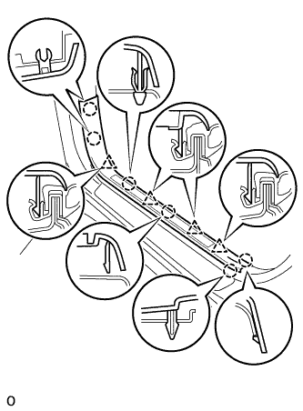
Engage the 6 claws and 4 clips, and install the front door scuff plate.
| 42. INSTALL FRONT DOOR SCUFF PLATE RH |
| 43. INSTALL REAR SEAT ASSEMBLY LH |
Place the rear seat assembly LH in the vehicle and align the adjuster pin with the hole on the vehicle side.
Move the rear seat assembly LH to the rearmost position by operating the rear seat track adjusting handle.
- NOTICE:
- Check that the seat is locked.
Temporarily install the front side of the rear seat assembly LH with the 2 bolts.
Recline the separate rear seatback forward by operating the rear seat lock control lever sub-assembly.
Move the rear seat assembly LH fully forward.
- NOTICE:
- Check that the seat is locked.
Temporarily install the rear side of the rear seat assembly LH with the 3 bolts.
Return the separate rear seatback to the upright position.
Move the rear seat assembly LH to the rearmost position by operating the rear seat track adjusting handle.
- NOTICE:
- Check that the seat is locked.
Fully tighten the 2 bolts on the front side of the rear seat assembly LH in the order of the inner side bolt and then the outer side bolt.
- Torque:
- 37 N*m{ 377 kgf*cm , 27 ft.*lbf }
Recline the separate rear seatback forward by operating the rear seat lock control lever sub-assembly.
Move the rear seat assembly LH fully forward.
- NOTICE:
- Check that the seat is locked.
Fully tighten the 3 bolts on the rear side of the rear seat assembly LH in the order of the inner rear side bolt, the inner front side bolt, and then the outer side bolt.
- Torque:
- 37 N*m{ 377 kgf*cm , 27 ft.*lbf }
Return the separate rear seatback to the upright position.
Move the rear seat assembly LH to the rearmost position by operating the rear seat track adjusting handle.
- NOTICE:
- Check that the seat is locked.
Install the floor anchor side of the fold seat stopper band assembly No.2 with the bolt.
- Torque:
- 9.0 N*m{ 92 kgf*cm , 80 in.*lbf }
Install the 3 clips.
| 44. INSTALL REAR SEAT TRACK BRACKET COVER |
| 45. INSTALL REAR SEAT ASSEMBLY RH |
Place the rear seat assembly RH in the vehicle and align the adjuster pin with the hole on the vehicle side.
Move the rear seat assembly RH to the rearmost position by operating the rear seat track adjusting handle.
- NOTICE:
- Check that the seat is locked.
Temporarily install the front side of the rear seat assembly RH with the 2 bolts.
Recline the separate rear seatback forward by operating the rear seat lock control lever sub-assembly.
Move the rear seat assembly RH fully forward.
- NOTICE:
- Check that the seat is locked.
Temporarily install the rear side of the rear seat assembly RH with the 3 bolts.
Return the separate rear seatback to the upright position.
Move the rear seat assembly RH to the rearmost position by operating the rear seat track adjusting handle.
- NOTICE:
- Check that the seat is locked.
Fully tighten the 2 bolts on the front side of the rear seat assembly RH in the order of the inner side bolt and then the outer side bolt.
- Torque:
- 37 N*m{ 377 kgf*cm , 27 ft.*lbf }
Recline the separate rear seatback forward by operating the rear seat lock control lever sub-assembly.
Move the rear seat assembly RH fully forward.
- NOTICE:
- Check that the seat is locked.
Fully tighten the 3 bolts on the rear side of the rear seat assembly RH in the order of the inner rear side bolt, the inner front side bolt, and then the outer side bolt.
- Torque:
- 37 N*m{ 377 kgf*cm , 27 ft.*lbf }
Return the separate rear seatback to the upright position.
Move the rear seat assembly RH to the rearmost position by operating the rear seat track adjusting handle.
- NOTICE:
- Check that the seat is locked.
Install the floor anchor side of the fold seat stopper band assembly No.1 with the bolt.
- Torque:
- 9.0 N*m{ 92 kgf*cm , 80 in.*lbf }
Install the 5 clips.
| 46. INSTALL REAR SEAT TRACK BRACKET COVER |
| 47. INSTALL DECK SIDE TRIM BOX LH |
Install the deck side trim box with the 2 clips.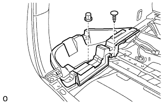
| 48. INSTALL DECK SIDE TRIM BOX RH |
| 49. INSTALL JACK CARRIER ASSEMBLY |
Install the jack carrier assembly, jack assembly and jack carrier support.
| 50. INSTALL REAR FLOOR FINISH PLATE |
Engage the 2 claws and 6 clips, and install the rear floor finish plate.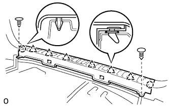
Install the 2 clips.
| 51. INSTALL BACK DOOR WEATHERSTRIP |
| 52. INSTALL NO.3 DECK BOARD SUB-ASSEMBLY |
Install the deck No.3 board sub-assembly with the 2 bolts and 2 nuts.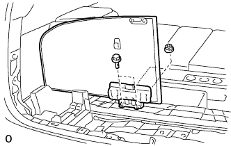
| 53. INSTALL NO.2 DECK BOARD SUB-ASSEMBLY |
Install the deck No.2 board sub-assembly with the 4 bolts and 2 nuts.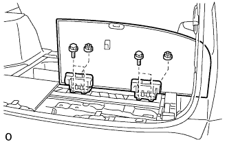
| 54. INSTALL DECK FLOOR BOX REAR |
Install the deck floor box rear with the 2 clips.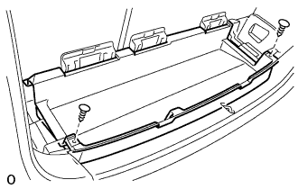
| 55. INSTALL DECK FLOOR BOX FRONT |
Install the deck floor box front with the 2 clips.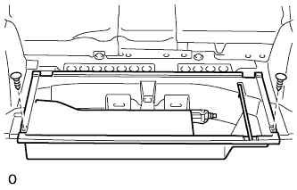
| 56. INSTALL DECK BOARD SUB-ASSEMBLY |
Install the deck board sub-assembly with the 2 bolt.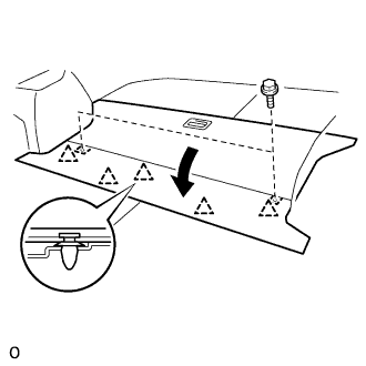
Engage the 5 clips.
| 57. INSTALL TONNEAU COVER ASSEMBLY |
| 58. CONNECT CABLE TO NEGATIVE BATTERY TERMINAL |
| 59. PERFORM INITIALIZATION |
- NOTICE:
- Some systems need initialization when disconnecting the cable from the negative battery terminal. (Click here)
| 60. INSPECT SLIDE ADJUSTER LOCK |
Check that the left and right adjusters lock simultaneously when sliding the seat.
If the left and right adjusters do not lock simultaneously, adjust by loosening the bolts securing the seat.