TERMINALS OF ECU
System information
| CHECK INSTRUMENT PANEL J/B ASSEMBLY (MULTIPLEX NETWORK BODY ECU) |
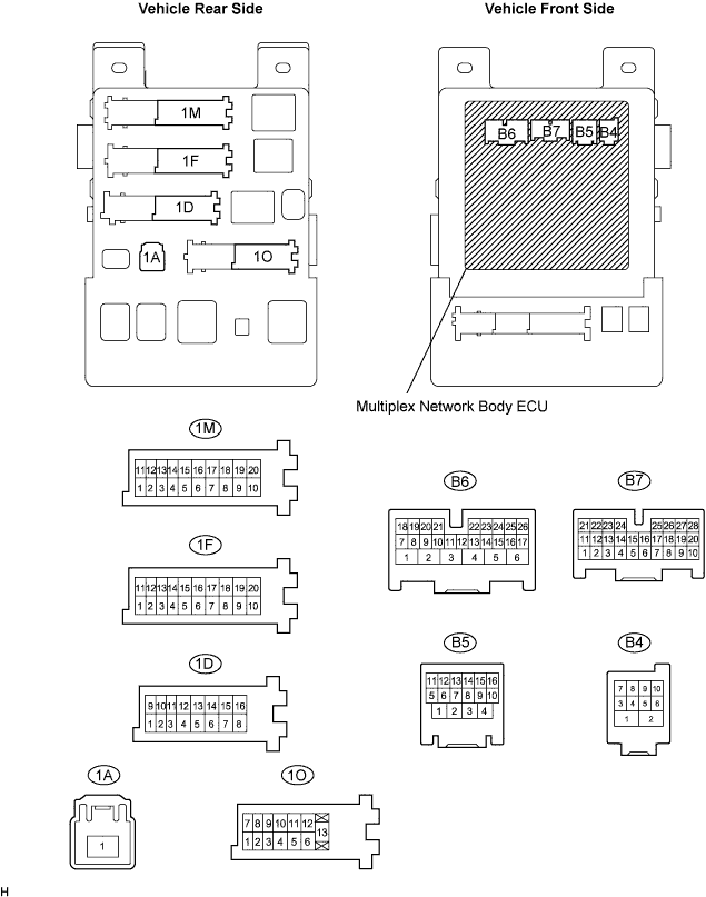

Disconnect the B4, B5, B6 and B7 ECU connectors.
Disconnect the 1A, 1D, 1F and 1O J/B connectors.
Measure the voltage and resistance between each terminal of the wire harness side connectors and body ground.
Standard: Symbols (Terminal No.)
Wiring Color
Terminal Description
Condition
Specified Condition
IG (1A-1) - Body ground
B - Body ground
Ignition power supply
Always
10 to 14 V
BECU (1D-10) - Body ground
W - Body ground
+B (BECU) power supply
Always
10 to 14 V
ALTB (1D-16) - Body ground
W*1 - Body ground
+B (power system, generator system) power supply
Always
10 to 14 V
ALTB (1D-16) - Body ground
R-Y*2 - Body ground
+B (power system, generator system) power supply
Always
10 to 14 V
GND1 (1F-10) - Body ground
W-B - Body ground
Ground
Always
Below 1 Ω
GND2 (1M-9) - Body ground
W-B - Body ground
Ground
Always
Below 1 Ω
LCTY (1O-7) - Body ground
B - Body ground
Rear LH courtesy switch
Rear door LH CLOSED (OFF) → OPEN (ON)
10 kΩ or higher → Below 1 Ω
HCTY (B4-10) - Body ground
R - Body ground
Engine hood courtesy switch
Engine hood CLOSED (OFF) → OPEN (ON)
10 kΩ or higher → Below 1 Ω
DCTY (B5-14) - Body ground
L - Body ground
Driver side courtesy switch
Driver side door CLOSED (OFF) → OPEN (ON)
10 kΩ or higher → Below 1 Ω
RCTY (B5-16) - Body ground
GR - Body ground
Rear RH courtesy switch
Rear door RH CLOSED (OFF) → OPEN (ON)
10 kΩ or higher → Below 1 Ω
KSW (B6-21) - Body ground
B - Body ground
Key unlock warning switch input
No key in ignition key cylinder (OFF) → Key inserted (ON)
10 kΩ or higher → Below 1 Ω
SSW1*3 (B7-10) - Body ground
W - Body ground
Intrusion sensor OFF switch
OFF switch ON
Below 1 Ω
SSW1*3 (B7-10) - Body ground
W - Body ground
Intrusion sensor OFF switch
OFF switch OFF
10 kΩ or higher
PCTY (B7-23) - Body ground
L - Body ground
Passenger side courtesy switch
Passenger side door CLOSED (OFF) → OPEN (ON)
10 kΩ or higher → Below 1 Ω
BCTY (B7-25) - Body ground
P - Body ground
Back door courtesy switch
Back door CLOSED (OFF) → OPEN (ON)
10 kΩ or higher → Below 1 Ω
- HINT:
- *1: LHD
- *2: RHD
- *3: Europe only
Reconnect the B4, B5, B6 and B7 ECU connectors.
Reconnect the 1A, 1D, 1F, 1M and 1O J/B connectors.
Measure the voltage between each terminal of the connectors and the body ground.
Standard: Symbols (Terminal No.)
Wiring Color
Terminal Description
Condition
Specified Condition
HORN (1D-11) - Body ground
R - Body ground
Vehicle horn drive
Vehicle horn is sounding
(Theft deterrent system is in alarm sounding state)
Pulse generation
(0 V ← → 12 V)
HAZ (B6-2) - Body ground
Y - Body ground
Hazard warning light drive
Answer-back OFF → Answer-back ON
Below 1 V → Pulse generation
IND (B6-24) - Body ground
W - Body ground
Security indicator output
Security indicator lights up (It lights up only for 30 sec. in alarm sounding state.
It flashes when immobilizer system is operating.)
3 to 6 V
S+B*1 (B7-11) - Body ground
BR - Body ground
Theft warning sensor input
Arming preparation state or armed state
10 to 14 V
S+B *1(B7-11) - Body ground
BR - Body ground
Theft warning sensor input
Disarmed state
Below 1 V
SSCL (B7-12) - Body ground
Y - Body ground
Theft warning siren
Self-power siren is sounding
(Theft deterrent system is in alarm sounding state)
Pulse generation
ISIF*1 (B7-13) - Body ground
P - Body ground
Theft warning sensor output
No moving object detected by sensor
10 to 14 V
ISIF*1 (B7-13) - Body ground
P - Body ground
Theft warning sensor output
Moving object detected by sensor during arming preparation state or armed state
Pulse generation
- HINT:
- *1: Europe only