Horn Circuit
Circuit diagnosis
DESCRIPTION
When the theft deterrent system is switched from the armed state to the alarm sounding state, the multiplex network body ECU turns on the HORN relay, causing the horns to sound.WIRING DIAGRAM
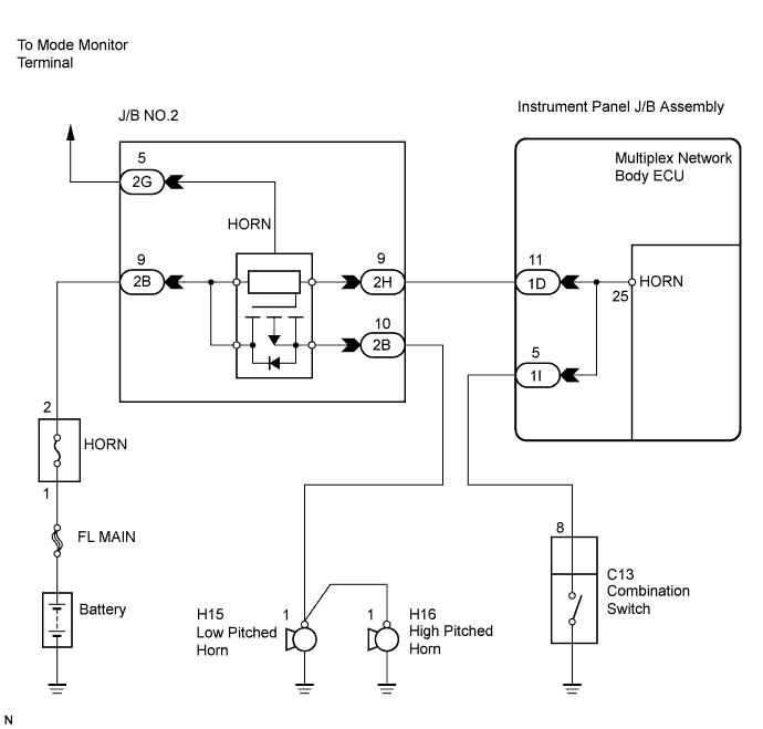

INSPECTION PROCEDURE
| 1. INSPECT HORN OPERATION |

Press the horn switch and check if the horns sound.
Result: Result
Go to
Horns sound
A
Horns do not sound
B
|
|
||||

| A | |
 |
| 2. READ DATA LIST BY INTELLIGENT TESTER |
Connect the intelligent tester to the DLC3.
Turn the ignition switch ON.
Turn the intelligent tester main switch on.
Select the item below in the DATA LIST and read the display on the tester.
BODY (Multiplex network body ECU): Item
Test Details
Diagnostic Note
Warning by Horn
Warning by horn ON/OFF
-
Result: Result
Go to
OFF
Buzzer operation is set to off by customization.
ON
A
| A | |
|
| 3. PERFORM ACTIVE TEST BY INTELLIGENT TESTER |
Connect the intelligent tester to the DLC3.
Turn the ignition switch ON.
Turn the intelligent tester main switch on.
Select the item below in the ACTIVE TEST and then check that the horns operate.
BODY (Multiplex network body ECU): Item
Test Details
Diagnostic Note
Vehicle Horn
Vehicle horn ON/OFF
-
- OK:
- The vehicle horns sound or stop correctly when operating it through the intelligent tester.
|
|
||||

| OK | ||
 |
||
| ||
| 4. CHECK HARNESS AND CONNECTOR (J/B NO.2 - INSTRUMENT PANEL J/B ASSEMBLY) |
Disconnect the 2H J/B No.2 connector and 1D instrument panel J/B connector.
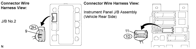
Measure the resistance according to the value(s) in the table below.
- Resistance:
Tester Connection
Specified Condition
2H-9 - 1D-11
Below 1 Ω
2H-9 or 1D-11 - Body ground
10 kΩ or higher
|
|
||||
| OK | ||
|
||
| ||