Diagnosis Circuit
Circuit diagnosis
DESCRIPTION
DTC output mode is set by connecting terminals TC and CG of the DLC3.DTCs are displayed by blinking the SRS warning light.
- HINT:
- Make sure that DTC B1281 has not been output. If DTC B1281 has been output, refer to the multiplex communication system.
- When each warning light stays blinking, a ground short in the wiring of terminal TC of the DLC3 or an internal ground short in each ECU is suspected.
- A DTC output mode signal is transmitted through BEAN to each ECU including the center airbag sensor assembly, except for the skid control ECU with actuator. Thus when all systems except the ABS system do not enter DTC output mode, it can be suspected that there is an ECM malfunction.
- Make sure that DTC B1281 has not been output. If DTC B1281 has been output, refer to the multiplex communication system.
WIRING DIAGRAM
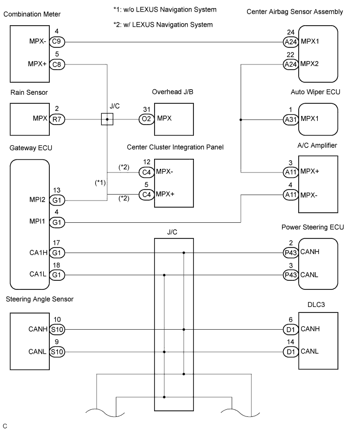

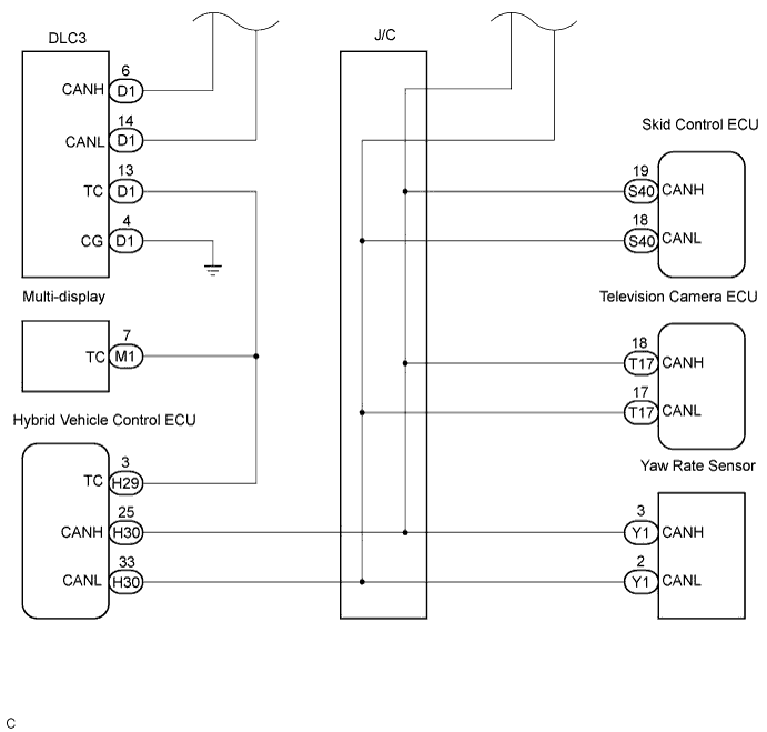
INSPECTION PROCEDURE
| 1. CHECK WIRE HARNESS (DLC3 - ECM) |

Turn the ignition switch to the LOCK position.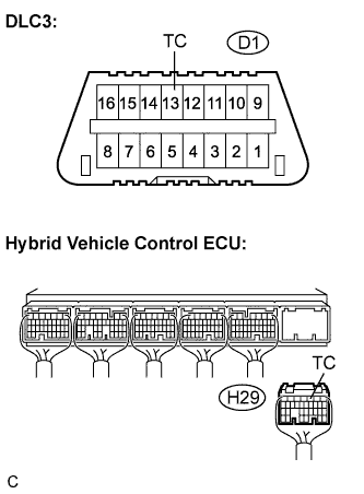
Disconnect the center airbag sensor assembly connector.
Measure the resistance according to the value(s) in the table below.
- Resistance:
Tester connection
Condition
Specified condition
D1-13 (TC) -
H29-3 (TC)
Always
Below 1 Ω
|
|
||||

| OK | |
 |
| 2. CHECK WIRE HARNESS (CG OF DLC3 - BODY GROUND) |
Measure the resistance according to the value(s) in the table below.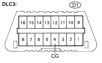
- Resistance:
Tester connection
Condition
Specified condition
D1-4 (CG) -
Body ground
Always
Below 1 Ω
|
|
||||
| OK | |
|
| 3. CHECK WIRE HARNESS (TC OF HYBRID VEHICLE CONTROL ECU - BODY GROUND) |
Measure the resistance according to the value(s) in the table below.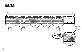
- Resistance:
Tester connection
Condition
Specified condition
H29-3 (TC) -
Body ground
Always
1 MΩ or higher
|
|
||||
| OK | |
|
| 4. REPLACE ECM |
Check that the ECM.
- Result:
- A:
- Normal system code is output.
- B:
- DTC is output.
- C:
- ECM does not set the DTC output mode.
|
|
||||
|
|
||||
| C | ||
 |
||
| ||