Vehicle Speed Signal Circuit between Multi-display and Combination Meter
Circuit diagnosis
DESCRIPTION
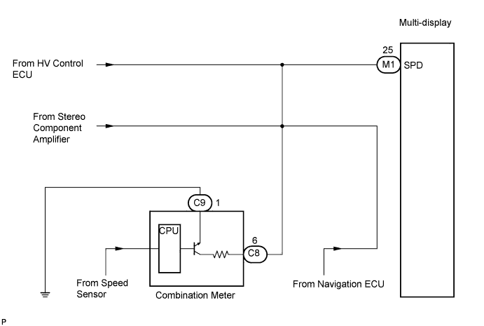
The multi-display performs switch operation control during driving by receiving a vehicle speed signal from the combination meter.- HINT:
- A voltage of 12 V or 5 V is output from each ECU and then input to the combination meter. The signal is changed to a pulse signal at the transistor in the combination meter. Each ECU controls the respective system based on the pulse signal.
- If a short occurs in an ECU, all systems in the diagram below will not operate normally.
- A voltage of 12 V or 5 V is output from each ECU and then input to the combination meter. The signal is changed to a pulse signal at the transistor in the combination meter. Each ECU controls the respective system based on the pulse signal.
WIRING DIAGRAM

INSPECTION PROCEDURE
| 1. CHECK OPERATION OF SPEEDOMETER |

Drive the vehicle and check if the function of the speedometer in the combination meter is normal.
- OK:
- Actual vehicle speed and the speed indicated on the speedometer are the same.
- HINT:
- The vehicle speed sensor is functioning normally when the indication on the speedometer is normal.
|
|
||||

| OK | |
 |
| 2. INSPECT MULTI-DISPLAY |
Disconnect the multi-display connector M1.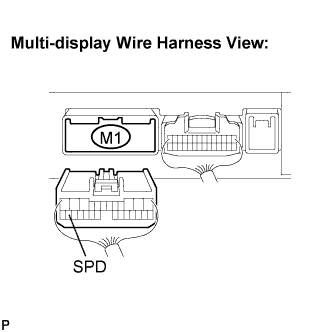
Measure voltage.
Jack up either one of the drive wheels.
Move the shift lever to the neutral position.
Turn the ignition switch to the ON position.
Measure the voltage between terminal SPD of the multi-display and body ground when the drive wheels are turned slowly.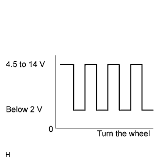
- OK:
- Voltage pulses as shown in the illustration.
|
|
||||
| NG | |
|
| 3. CHECK HARNESS AND CONNECTOR (COMBINATION METER - MULTI-DISPLAY) |
Disconnect the multi-display connector M1 and combination meter connector C8.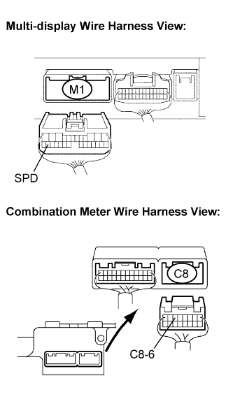
Measure the resistance according to the value(s) in the table below.
- Resistance:
Tester connection
Condition
Specified condition
SPD - C8-6
Ignition switch OFF
Below 1 Ω
|
|
||||
| OK | |
|
| 4. CHECK HARNESS AND CONNECTOR (COMBINATION METER - MULTI-DISPLAY) |
Disconnect the multi-display connector M1 and combination meter connector C8.
Measure the resistance according to the value(s) in the table below.
- Resistance:
Tester connection
Condition
Specified condition
SPD - Body ground
Ignition switch OFF
10 kΩ or higher
- HINT:
- If the resistance between terminal SPD and body ground is less than 10 kΩ, there may be a short in a wire harness, connector, or ECU.
|
|
||||
| OK | ||
 |
||
| ||