ON-VEHICLE INSPECTION
Inspection
| INSPECT INTEGRATION CONTROL & PANEL ASSEMBLY |

Disconnect the C4 connector.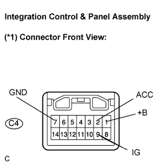

Measure the voltage between the terminals according to the value(s) in the table below.
- Standard Voltage:
Tester Connection
Condition
Specified Condition
C4-1 (+B) -
Body ground
Always
10 to 14 V
C4-2 (ACC) -
Body ground
Turn the ignition switch to the off → ACC or ON position
Below 1 V →
10 to 14 V
C4-9 (IG+) -
Body ground
Turn the ignition switch to the off → ACC or ON position
Below 1 V →
10 to 14 V
Measure the resistance between the terminals according to the value(s) in the table below.
- Standard Resistance:
Tester Connection
Condition
Specified Condition
C4-7 (GND) -
Body ground
Always
Below 1 Ω
- HINT:
- If the value is not as specified, replace the integration control & panel assembly.
| INSPECT MULTI-DISPLAY |
Disconnect the M5 connector.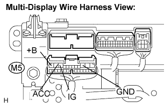
Measure the voltage between the terminals according to the value(s) in the table below.
- Standard Voltage:
Tester Connection
Condition
Specified Condition
M5-12 (+B) -
Body ground
Always
10 to 14 V
M5-11 (ACC) -
Body ground
Turn the ignition switch to the off → ACC or ON position
Below 1 V →
10 to 14 V
M5-10 (IG) -
Body ground
Turn the ignition switch to the off → ACC or ON position
Below 1 V →
10 to 14 V
Measure the resistance between the terminals according to the value(s) in the table below.
- Standard Resistance:
Tester Connection
Condition
Specified Condition
M5-3 (GND) -
Body ground
Always
Below 1 Ω
- HINT:
- If the value is not as specified, replace the multi-display.