TERMINALS OF ECU
System information
| CHECK INSTRUMENT PANEL J/B ASSEMBLY (BODY ECU) |
Disconnect the 1D, 1F, 1M, and B7 connectors.
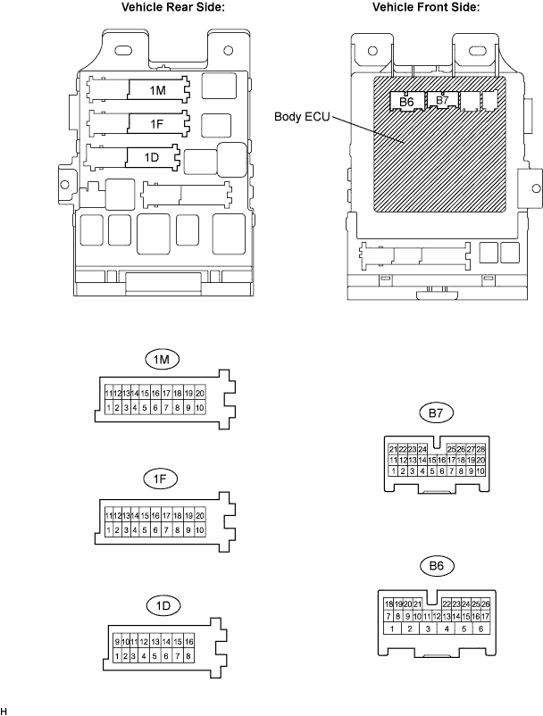

Measure the voltage and resistance according to the value(s) in the table below.
- Standard voltage and resistance:
Symbols
(Terminal No.)
Wiring Color
Terminal Description
Condition
Specified Condition
BECU (1D-10) - Body ground
W - Body ground
+B (BECU) power supply
Constant
10 to 14 V
GND1 (1F-10) - Body ground
W-B - Body ground
Ground
Constant
Below 1 Ω
GND2 (1M-9) - Body ground
W-B - Body ground
Ground
Constant
Below 1 Ω
BDSU (B7-3) - Body ground
W - Body ground
Back door opener switch (outside handle switch) input
Back door opener switch
OFF → ON
10 kΩ or higher →
Below 1 Ω
- HINT:
- If the result is not as specified, there may be a malfunction on the wire harness side.
Reconnect the J/B and ECU connectors and measure the voltage according to the value(s) in the table below.
- Standard voltage:
Symbols
(Terminal No.)
Wiring Color
Terminal Description
Condition
Specified Condition
TR+ (B6-1)* - Body ground
BR - Body ground
Back door lock motor drive output
Back door opener switch (outside handle switch)
OFF → ON
Below 1 V →
10 to 14 V →
Below 1 V
- HINT:
- *: w/o Power Back Door
- If the result is not as specified, the J/B (body ECU) may have a malfunction.
- *: w/o Power Back Door
| CHECK POWER BACK DOOR ECU (w/ Power back door system) |
Disconnect the P10 and P11 ECU connectors.
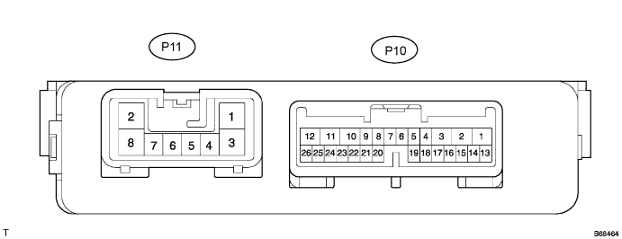
Measure the voltage and resistance according to the value(s) in the table below.
- Standard voltage and resistance:
Symbols
(Terminal No.)
Wiring Color
Terminal Description
Condition
Specified Condition
ECUB (P10-10) - Body ground
BR - Body ground
ECU (ECUB) power supply
Constant
10 to 14 V
B (P11-2) - Body ground
Y - Body ground
+B (ECUB) power supply
Constant
10 to 14 V
GND (P11-8) - Body ground
W-B - Body ground
Ground
Constant
Below 1 Ω
- HINT:
- If the result is not as specified, there may be a malfunction on the wire harness side.
Reconnect the ECU connectors and measure the voltage according to the value(s) in the table below.
- Standard voltage:
Symbols
(Terminal No.)
Wiring Color
Terminal Description
Condition
Specified Condition
DC+ (P10-12) - Body ground
G - Body ground
Back door lock motor drive output (Close)
Back door OPEN →
Not completely closed →
Motor in normal rotation →
Motor in reverse rotation →
Operation completed (Back door CLOSED)
Below 1 V →
Below 1 V →
10 to 14 V →
Below 1 V →
Below 1 V →
DC- (P10-11) - Body ground
B - Body ground
Back door lock motor drive output (Release)
Back door OPEN →
Not completely closed →
Motor in normal rotation →
Motor in reverse rotation →
Operation completed (Back door CLOSED)
Below 1 V →
Below 1 V →
Below 1 V →
10 to 14 V →
Below 1 V →
- HINT:
- If the result is not as specified, the ECU may have a malfunction.