Power Meter Gauge Malfunction
Circuit diagnosis
WIRING DIAGRAM
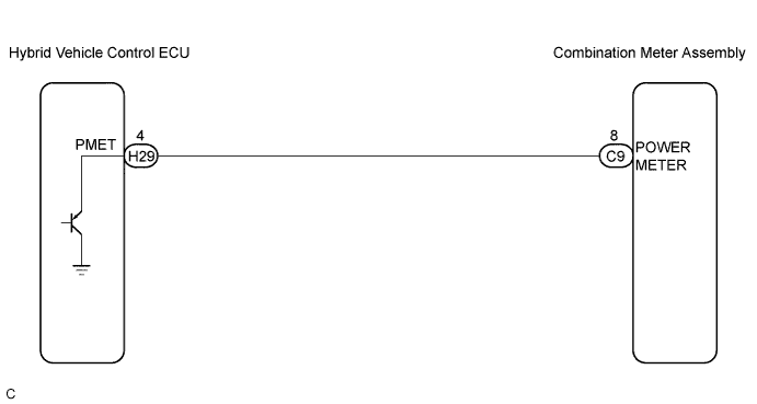

INSPECTION PROCEDURE
| 1. PERFORM ACTIVE TEST BY INTELLIGENT TESTER |

Operate the intelligent tester according to the steps on the display and select "ACTIVE TEST".
METER Item
Test Details
Diagnostic Note
Power Meter Operation
0 / 50 / 100 / 150 / 200 kW
Confirm that the vehicle is stopped, engine idling.
- OK:
- Needle indication is normal.
|
|
||||

| OK | |
 |
| 2. CHECK HARNESS AND CONNECTOR (BETWEEN COMBINATION METER AND HYBRID VEHICLE CONTROL ECU) |
Disconnect the C9 and H29 connectors.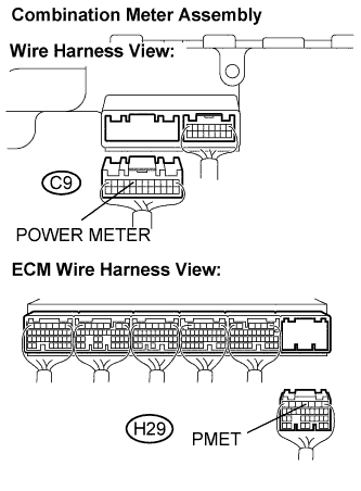
Measure the resistance according to the value(s) in the table below.
- Standard Resistance:
Tester Connection
Condition
Specified Condition
C9-8 (POWER METER) - H29-4 (PMET)
Always
Below 1 Ω
C9-8 (POWER METER) - Body ground
Always
10 kΩ or higher
|
|
||||
| OK | |
|
| 3. INSPECT COMBINATION METER ASSEMBLY |
Check the input signal waveform.
Remove the combination meter assembly with connector still connected.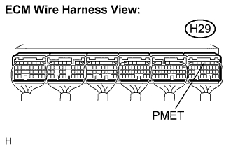
Connect the oscilloscope to the terminals H29-4 (PMET) and body ground.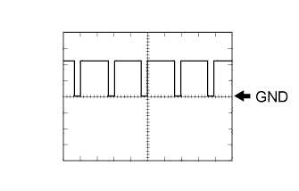
Start the engine.
Check the signal waveform according to he condition(s) in the table below.
OK Item
Condition
Tool setting
1 V/DIV., 2 μs/DIV.
Vehicle condition
Turn the ignition switch to the ON position.
|
|
||||
| NG | ||
 |
||
| ||