Hybrid Vehicle Control ECU Communication Stop Mode
Circuit diagnosis
DESCRIPTION
| Detection Item |
Symptom |
Suspected Area |
| HYBRID VEHICLE CONTROL ECU COMMUNICATION STOP MODE |
|
|
WIRING DIAGRAM
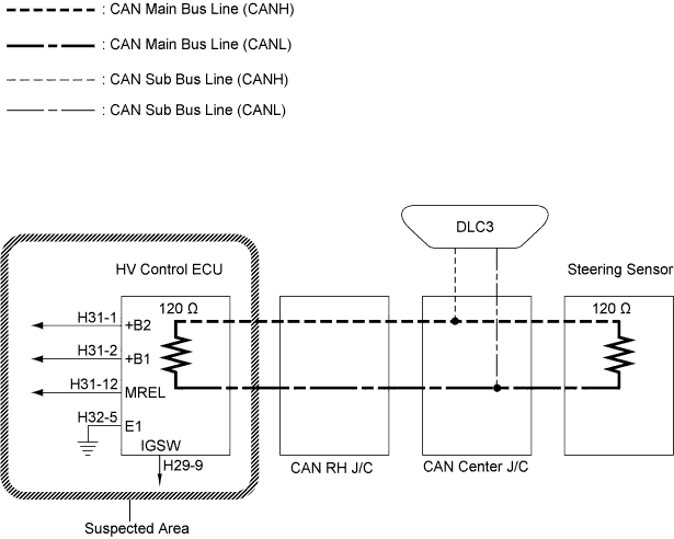

INSPECTION PROCEDURE
| 1. CHECK WIRE HARNESS (+B1, +B2, IGSW, MREL, E1) |

Measure the resistance according to the value(s) in the table below.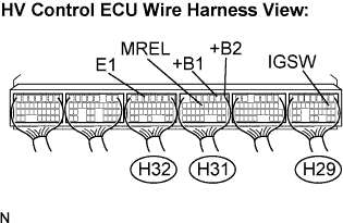
- Standard Resistance:
Tester Connection
Condition
Specified Value
H32-5 (E1) - Body ground
Always
Below 1 Ω
Measure the voltage according to the value(s) in the table below.
- Standard Voltage:
Tester Connection
Condition
Specified Value
H29-9 (IGSW) - Body ground
Ignition switch on
10 to 14 V
H31-1 (+B2) - Body ground
Always
10 to 14 V
H31-2 (+B1) - Body ground
Always
10 to 14 V
H31-12 (MREL)- Body ground
Ignition switch on
10 to 14 V
|
|
||||

| OK | ||
 |
||
| ||