Power Source Circuit
Circuit diagnosis
DESCRIPTION
This circuit provides power to operate the windshield wiper relay assembly.WIRING DIAGRAM
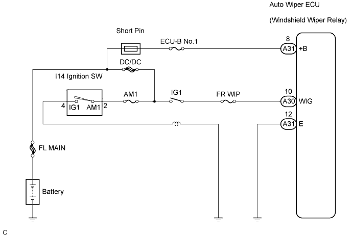

INSPECTION PROCEDURE
| 1. INSPECT FUSE |

Inspect the AM1, FR WIP, ECU-B and INP-J/B fuses.
Measure the resistance between each terminal.
- Standard resistance:
- Below 1Ω
|
|
||||

| OK | |
 |
| 2. INSPECT RELAY |
Inspect IG1 relay continuity.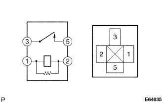
Measure the resistance according to the value(s) in the table below.
- Standard resistance:
Terminal No.
Specified Condition
3 - 5
10 kΩ or higher
Below 1 Ω
(When battery voltage is applied to terminals 1 and 2)
|
|
||||
| OK | |
|
| 3. CHECK HARNESS AND CONNECTOR (AUTO WIPER ECU - BODY GROUND) |
Disconnect the connector from the auto wiper ECU.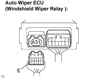
Measure the resistance according to the value(s) in the table below.
- Standard resistance:
Tester Connecting
Condition
Specified Condition
E - Body ground
Always
Below 1 Ω
|
|
||||
| OK | |
|
| 4. INSPECT WINDSHIELD WIPER RELAY ASSEMBLY (POWER SOURCE CIRCUIT) |
Disconnect the connector from the auto wiper ECU.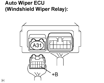
Measure the voltage according to the value(s) in the table below.
- Standard voltage:
Tester Connection
Condition
Specified Condition
+B - Body ground
Always
10 to 14V
|
|
||||
| OK | |
|
| 5. INSPECT WINDSHIELD WIPER RELAY ASSEMBLY |
Disconnect the connector from the auto wiper ECU.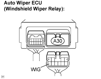
Measure the voltage according to the value(s) in the table below.
- Standard voltage:
Tester Connection
Condition
Specified Condition
WIG - Body ground
Ignition Switch
OFF → ON
Below 1 V → 10 to 14 V
|
|
||||

| OK | ||
 |
||
| ||
| 6. INSPECT IGNITION SWITCH |
Disconnect the connector from the ignition switch.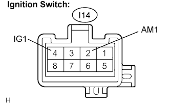
Measure the resistance according to the value(s) in the table below.
- Standard resistance:
Tester connection
Condition
Specified value
AM1 - IG1
Ignition switch
OFF→ON
10 kΩ or higher → Below 1 Ω
|
|
||||
| OK | ||
|
||
| ||