INSTALLATION
Removal / installation
| 1. INSTALL SKID CONTROL ECU ASSEMBLY |

Temporarily install the skid control ECU assembly with the clip.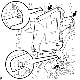

Connect the skid control ECU assembly with the 2 bolts.
- Torque:
- 5.0 N*m{ 51 kgf*cm , 44 in.*lbf }
Connect the skid control ECU assembly connectors.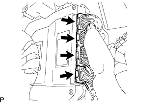
| 2. INSTALL AIR CONDITIONER AMPLIFIER ASSEMBLY |
Install the air conditioner amplifier assembly with the 2 nuts.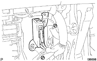
| 3. INSTALL GLOVE COMPARTMENT DOOR ASSEMBLY (for LHD) |
Connect the connectors.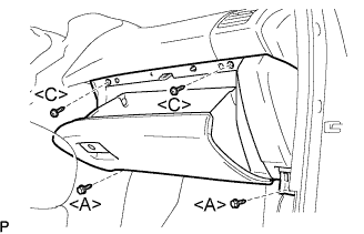
Install the 2 bolts <A>, the 2 screws <C>, and the glove compartment door assembly.
| 4. INSTALL INSTRUMENT PANEL NO.2 UNDER COVER SUB-ASSEMBLY (for LHD) |
Connect the connectors.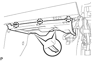
Engage the 3 claws and install the instrument panel No.2 under cover sub-assembly.
| 5. INSTALL DRIVER SIDE KNEE AIRBAG ASSEMBLY (for RHD) |
Install the driver side knee airbag assembly with the 4 bolts.
- Torque:
- 7.6 N*m{ 78 kgf*cm , 68 in.*lbf }
Connect the connector to the driver side knee airbag assembly.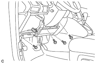
- NOTICE:
- When handling the airbag connector, take care not to damage the airbag wire harness.
| 6. INSTALL INSTRUMENT PANEL FINISH PANEL SUB-ASSEMBLY LOWER (for RHD) |
Connect the connectors.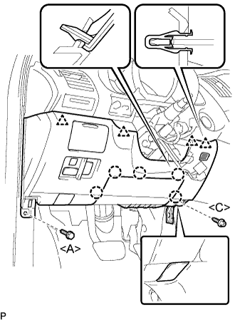
Engage the 5 claws and the 4 clips.
Connect the hood lock control cable assembly.
Install the bolt <A>, the screw <C>, and the instrument panel finish panel sub-assembly lower.
| 7. INSTALL COWL SIDE TRIM SUB-ASSEMBLY RH |
- HINT:
- Use the same procedures for the RH side and the LH side.
| 8. INSTALL FRONT DOOR SCUFF PLATE RH |
- HINT:
- Use the same procedures for the RH side and the LH side.
| 9. CONNECT CABLE TO NEGATIVE BATTERY TERMINAL |
| 10. INSPECT SRS WARNING LIGHT |
| 11. PERFORM YAW RATE SENSOR ZERO POINT CALIBRATION |
| 12. INSPECT VSC WARNING LIGHT |
| 13. PERFORM LINEAR VALVE OFFSET LEARNING |
When the skid control ECU is replaced, perform linear valve offset learning.
(Click here)
| 14. CHECK AND CLEAR DTC |
| 15. PERFORM INITIALIZATION |
(Click here)