P3105 Problem in serial communication between the battery smart unit and HV control ECU (1 trip)
Diagnostic trouble codes
DESCRIPTION
The battery smart unit detects the HV battery conditions (voltage, current, and temperature) and the battery cooling fan voltage, and sends the detected signals to the HV control ECU via the serial communication system.| DTC No. |
DTC Detection Condition |
Trouble Area |
| P3105 |
Problem in serial communication between the battery smart unit and HV control ECU (1 trip) |
Wire harness or connector HV control ECU Battery smart unit |
MONITOR DESCRIPTION
If a malfunction in communication line between the battery smart unit and HV control ECU is detected, the HV control ECU illuminates the MIL and sets a DTC.WIRING DIAGRAM
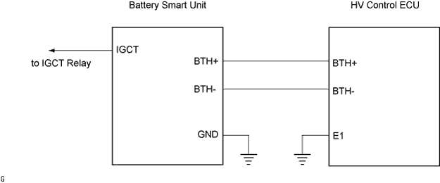

INSPECTION PROCEDURE
- CAUTION:
- If the battery cover is removed, install it before turning the ignition switch to the ON position (or putting the vehicle into the READY-on state). If the ignition switch is turned to the ON position (or the vehicle is put into the READY-on state) with the battery cover removed, P3105 may be output.
- Before inspecting the high-voltage system, take safety precautions to prevent electrical shocks, such as wearing insulated gloves and removing the service plug grip. After removing the service plug grip, put it in your pocket to prevent other technicians from reconnecting it while you are working on the high-voltage system.
- After disconnecting the service plug grip, wait for at least 5 minutes before touching any of the high-voltage connectors or terminals.
- If the battery cover is removed, install it before turning the ignition switch to the ON position (or putting the vehicle into the READY-on state). If the ignition switch is turned to the ON position (or the vehicle is put into the READY-on state) with the battery cover removed, P3105 may be output.
- HINT:
- At least 5 minutes is required to discharge the high-voltage capacitor inside the w/ converter inverter assembly.
| 1. INSPECT HYBRID VEHICLE CONTROL ECU |

- HINT:
- By using the oscilloscope function in the intelligent tester, inspection of the function between the HV control ECU and battery smart unit can be conducted.
Connect the intelligent tester to the HV control ECU terminals specified in the table below, set the tester to the oscilloscope function, and check the waveform.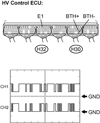
Item
Contents
Terminal
CH1: BTH+ (H30-19) - E1 (H32-5)
CH2: BTH- (H30-30) - E1 (H32-5)
Equipment Setting
2V/DIV, 500μs/DIV
Condition
Ignition switch ON
- Standard:
- The waveform in the illustration can be measured.
- HINT:
- The waveform shown in the illustration varies depending on the contents of the communication.
|
|
||||

| NO | |
 |
| 2. CHECK HARNESS AND CONNECTOR (HV CONTROL ECU - BATTERY PACK WIRE) |
Disconnect the H30 connector from the HV control ECU.
Disconnect the BL1 connector shown in the illustration.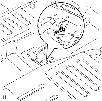
Measure the resistance according to the value(s) in the table below.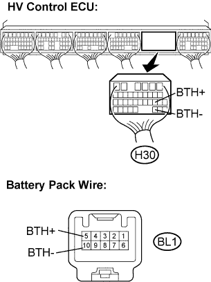
- Standard Resistance (Check for open):
Tester Connection
Specified Condition
BTH+ (H30-19) - BTH+ (BL1-5)
Below 1 Ω
BTH- (H30-30) - BTH- (BL1-10)
Below 1 Ω
- Standard Resistance (Check for short):
Tester Connection
Specified Condition
BTH+ (H30-19) - Body ground
10 kΩ or higher
BTH- (H30-30) - Body ground
10 kΩ or higher
|
|
||||
| OK | |
|
| 3. CHECK HARNESS AND CONNECTOR (BATTERY PACK WIRE) |
Connect the H30 connector to the HV control ECU.
Measure the voltage according to the value(s) in the table below when the ignition switch is in the ON position.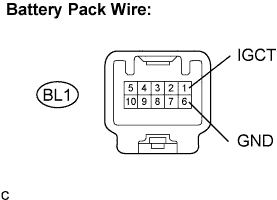
- Standard Voltage:
Tester Connection
Specified Condition (V)
IGCT (BL1-1) - GND (BL1-6)
9 to 14 V
|
|
||||
| OK | |
|
| 4. INSPECT BATTERY PACK WIRE |
- CAUTION:
- Be sure to wear insulated gloves and protective goggles.
Remove the service plug grip. (Click here)
Remove the battery cover. (Click here)
Disconnect the B26 connector from the battery smart unit.
Measure the resistance according to the value(s) in the table below.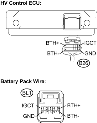
- Standard Resistance (Check for open):
Tester Connection
Specified Condition
BTH+ (B26-7) - BTH+ (BL1-5)
Below 1 Ω
BTH- (B26-14) - BTH- (BL1-10)
Below 1 Ω
IGCT (B26-1) - IGCT (BL1-1)
Below 1 Ω
GND (B26-8) - GND (BL1-6)
Below 1 Ω
- Standard Resistance (Check for short):
Tester Connection
Specified Condition
BTH+ (B26-7) - Body ground
10 kΩ or higher
BTH- (B26-14) - Body ground
10 kΩ or higher
IGCT (B26-1) - Body ground
10 kΩ or higher
GND (B26-8) - Body ground
10 kΩ or higher
|
|
||||
| OK | ||
 |
||
| ||