Headlight (HI-BEAM) Circuit
Circuit diagnosis
DESCRIPTION
The body ECU receives headlight HI switch information from the combination switch, and controls the DIM relay. The DIM relay installed in the power distributor.System diagram of the power distributor (Click here).
System description of the power distributor (Click here).
WIRING DIAGRAM
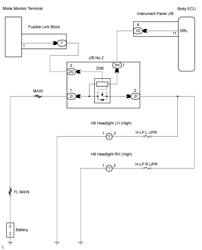

INSPECTION PROCEDURE
| 1. PERFORM ACTIVE TEST BY INTELLIGENT TESTER |

Connect the intelligent tester to DLC3.
Turn the ignition switch ON and push the intelligent tester main switch ON.
Select the item below in the ACTIVE TEST and then check that the relay operates.
BODY NO.1 Item
Test Details
Diagnostic Note
Dimmer Signal
Turn Dimmer relay ON/OFF
-
|
|
||||

| OK | ||
 |
||
| ||
| 2. CHECK HARNESS AND CONNECTOR (POWER SOURCE CIRCUIT) |
Disconnect the connector from the J/B No.2 (power distributor).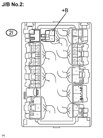
Measure the voltage according to the value(s) in the table below.
- Voltage:
Tester connection
Condition
Specified value
2I-1 (+B) - Body ground
Always
10 to 14 V
|
|
||||

| OK | |
 |
| 3. CHECK MODE MONITOR TERMINAL (DIM RELAY) |
Preparation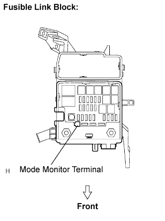
Connect the connector.
Remove the cover of the fusible link block assembly.
Set the vehicle to the following conditions:
- Ignition switch ON
- Headlight dimmer switch HI (FLASH)
- Ignition switch ON
Check voltage
Measure the voltage between the Mode Monitor Terminal and body ground.
- Voltage:
Result
Proceed to
0 V or Approx. 12V
A
Approx. 6.2 V
B
Approx. 2.0 V
C
|
|
||||
|
|
||||
| A | |
|
| 4. CHECK HARNESS AND CONNECTOR (J/B NO.2 - MODE MONITOR TERMINAL) |
Disconnect the 2G connector from the J/B No.2.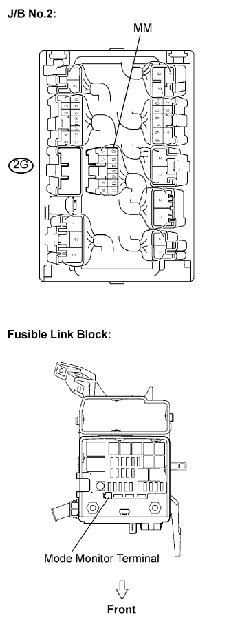
Measure the resistance according to the value(s) in the table below.
- Resistance:
Tester connection
Condition
Specified value
2G-5 - Mode monitor terminal
Always
Below 1 Ω
2G-5 - Body ground
Always
10 kΩ or higher
|
|
||||
| OK | |
|
| 5. INSPECT JUNCTION BLOCK NO.2 (DIM RELAY) |
Turn the ignition switch to OFF position.
Remove the J/B No.2.
Inspect the DIM relay.
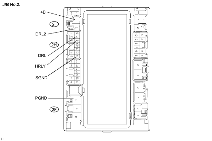
Connect the positive battery lead to terminal +B of the J/B No.2 and the negative lead to terminal SGND, PGND.
Symbols (terminals No.)
Connection
+B (2I-1) - SGND (2H-13), PGND (2F-1)
Positive - Negative
Measure the voltage according to the value(s) in the table below.
- Voltage:
Tester Connection
Specified Condition
DRL2 (2I-2) - Battery negative terminal
Below 1 V
Connect the battery negative lead to terminal DRL of the J/B No.2.
Symbols (terminals No.)
Connection
DRL (2H-7)
Negative
Measure the voltage according to the value(s) in the table below.
- Voltage:
Tester Connection
Specified Condition
DRL2 (2I-2) - Battery negative terminal
10 to 14 V
|
|
||||
| OK | |
|
| 6. CHECK HARNESS AND CONNECTOR (J/B NO.2 - INSTRUMENT PANEL J/B) |
Disconnect the connectors from the instrument panel J/B.
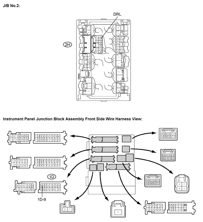
Measure the resistance according to the value(s) in the table below.
- Resistance:
Tester connection
Condition
Specified value
2H-7 (DRL) - 1D-9
Always
Below 1 Ω
2H-7 (DRL) - Body ground
Always
10 kΩ or higher
|
|
||||
| OK | |
|
| 7. CHECK HARNESS AND CONNECTOR (J/B NO.2 - BULB) |
Disconnect the connectors from the J/B No.2 (power distributor) and headlight bulb.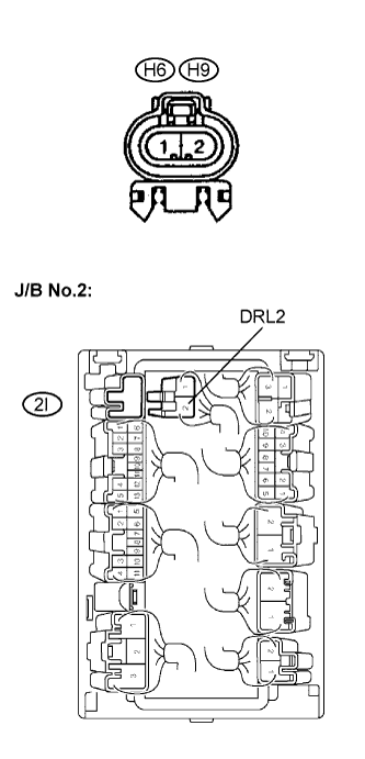
Measure the resistance according to the value(s) in the table below.
- Resistance:
Tester connection
Condition
Specified value
2I-2 (DRL2) - H6-2 (Headlight LH)
Always
Below 1 Ω
2I-2 (DRL2) - H9-2 (Headlight RH)
Always
Below 1 Ω
2I-2 (DRL2) - Body ground
Always
10 kΩ or higher
|
|
||||
| OK | |
|
| 8. CHECK HARNESS AND CONNECTOR (BULB - BODY GROUND) |
Measure the resistance according to the value(s) in the table below.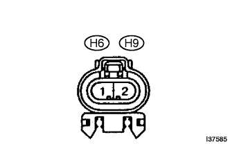
- Resistance:
Tester connection
Condition
Specified value
H6-1 (Headlight LH) - Body ground
Always
Below 1 Ω
H9-1 (Headlight RH) - Body ground
Always
Below 1 Ω
|
|
||||
| OK | ||
|
||
| ||
| 9. CHECK MODE MONITOR TERMINAL (SHORT CIRCUIT DRIVEN SIDE BY RELAY) |
Disconnect the 2I connector from the J/B No.2.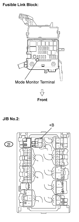
Connect the battery positive lead to terminal 2I-1 on the J/B side and negative lead to the body ground.
Check voltage
Measure the voltage between the Mode Monitor Terminal and body ground.
- Voltage:
Result
Proceed to
Approx. 6.2 V
A
Approx. 2.0 V
B
|
|
||||
| A | ||
|
||
| ||