TERMINALS OF ECU
System information
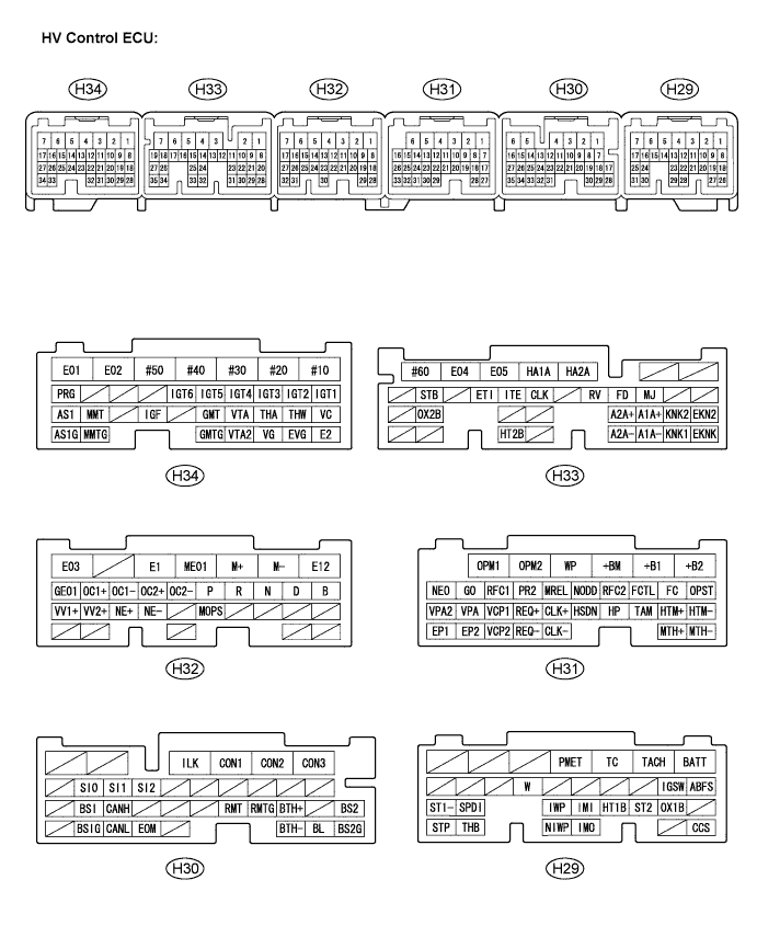

| Symbols (Terminal No.) |
Wiring Color |
Terminal Description |
Condition |
Standard Voltage (V) |
| BATT (H29-1) - E1(H32-5) |
GR - BR |
Constant power source |
Always |
10 to 14 |
| TC(H29-3) - E1 (H32-5) |
BR - BR |
Diagnostic terminal |
Ignition switch ON |
10 to 14 |
| PMET (H29-4) - E1 (H32-5) |
SB - BR |
Power meter signal |
Ignition switch ON |
Pulse generation (Waveform 1) |
| ABFS(H29-8) - E1 (H32-5) |
G - BR |
Airbag activation signal |
READY-on state (2 seconds after ACC ON) |
Pulse generation (Waveform 2) |
| IGSW (H29-9) - E1 (H32-5) |
G - BR |
IG signal |
Ignition switch ON |
10 to 14 |
| ST2 (H29-20) - E1 (H32-5) |
Y - BR |
Starter signal |
Ignition switch ON |
0 to 1.5 |
| IWP (H29-23) - E1 (H32-5) |
Y - BR |
HV water pump signal |
READY-on state |
10 to 14 |
| NIWP (H29-29) - E1 (H32-5) |
BR - BR |
HV water pump signal |
READY-on state |
Pulse generation (Waveform 3) |
| SPDI (H29-24) - E1 (H32-5) |
LG - BR |
Vehicle speed signal |
Approximately 20 km/h (12 mph) |
Pulse generation (Waveform 4) |
| ST1- (H29-25) - E1 (H32-5) |
LG - BR |
Brake cancel switch |
Ignition switch ON, brake pedal depressed |
Below 0.5 |
| ST1- (H29-25) - E1 (H32-5) |
LG - BR |
Brake cancel switch |
Ignition switch ON, brake pedal released |
10 to 14 |
| IMI (H29-22) - E1 (H32-5) |
GR - BR |
Immobilizer communication |
Immobilizer communicating |
Pulse generation (Waveform 5) |
| IMO (H29-28) - E1 (H32-5) |
L - BR |
Immobilizer communication |
Immobilizer communicating |
Pulse generation (Waveform 5) |
| THB (H29-30) - E2 (H34-28) |
R - BR |
Auxiliary battery temperature sensor signal |
Auxiliary battery temperature 25 °C |
1.8 to 2.4 |
| THB (H29-30) - E2 (H34-28) |
R - BR |
Auxiliary battery temperature sensor signal |
Auxiliary battery temperature 25 °C |
0.7 to 1.3 |
| STP (H29-31) - E1 (H32-5) |
O - BR |
Stop light switch |
Brake pedal depressed |
10 to 14 |
| STP (H29-31) - E1 (H32-5) |
O - BR |
Stop light switch |
Brake pedal released |
Below 5 |
| CON3 (H30-1) - E1 (H32-5) |
BR - BR |
System main relay |
Ignition switch OFF to READY-on state |
Pulse generation (Waveform 6) |
| CON2 (H30-2) - E1 (H32-5) |
GR - BR |
System main relay |
Ignition switch OFF to READY-on state |
Pulse generation (Waveform 6) |
| CON1 (H30-3) - E1 (H32-5) |
B - BR |
System main relay |
Ignition switch OFF to READY-on state |
Pulse generation (Waveform 6) |
| ILK (H30-4) - E1 (H32-5) |
W - BR |
Interlock switch |
Ignition switch ON, inverter cover and service plug grip installed correctly |
Below 1 |
| ILK (H30-4) - E1 (H32-5) |
W - BR |
Interlock switch |
Ignition switch ON, inverter cover and service plug grip detached |
10 to 14 |
| SI2 (H30-13) - E1 (H32-5) |
LG - BR |
HV battery blower fan |
Ignition switch ON, during active test |
Pulse generation (Waveform 7) |
| SI1 (H30-14) - E1 (H32-5) |
R - BR |
HV battery blower fan |
Ignition switch ON, during active test |
Pulse generation (Waveform 7) |
| SI0 (H30-15) - E1 (H32-5) |
Y - BR |
HV battery blower fan |
Ignition switch ON, during active test |
Pulse generation (Waveform 7) |
| BTH+ (H30-19) - E1 (H32-5) |
Y - BR |
Communication from battery to HV |
Ignition switch ON |
Pulse generation (Waveform 8) |
| BTH- (H30-30) - E1 (H32-5) |
BR - BR |
Communication from battery to HV |
Ignition switch ON |
Pulse generation (Waveform 8) |
| RMT (H30-21) - RMTG (H30-20) |
B - W |
Rear Motor temperature sensor |
Refer to DATA LIST |
- |
| CANH (H30-25) - E1 (H32-5) |
B - BR |
CAN communication system |
Ignition switch ON |
Pulse generation (Waveform 9) |
| CANL (H30-33) - E1 (H32-5) |
W - BR |
CAN communication system |
Ignition switch ON |
Pulse generation (Waveform 9) |
| +B2 (H31-1) - E1 (H32-5) |
R - BR |
Power source |
Ignition switch ON |
10 to 14 |
| +B1 (H31-2) - E1 (H32-5) |
R - BR |
Power source |
Ignition switch ON |
10 to 14 |
| OPM2 (H31-5) - E1 (H32-5) |
P - BR |
Oil pump |
READY-on state |
10 to 14 |
| OPM1 (H31-6) - E1 (H32-5) |
Y - BR |
Oil pump |
READY-on state |
Pulse generation (Waveform 10) |
| OPST (H31-7) - E1 (H32-5) |
L - BR |
Oil pump |
READY-on state |
Pulse generation (Waveform 10) |
| FCTL (H31-9) - E1 (H32-5) |
O - BR |
Cooling fan relay |
Ignition switch ON |
10 to 14 |
| RFC2 (H31-10) - E1 (H32-5) |
L - BR |
Radiator fan |
Ignition switch ON, engine started |
Pulse generation (Waveform 11) |
| NODD (H31-11) - E1 (H32-5) |
W - BR |
DC/DC operation monitor/ stop request signal |
Converter operating normally |
5 to 7 |
| NODD (H31-11) - E1 (H32-5) |
W - BR |
DC/DC operation monitor/ stop request signal |
Converter not operating normally |
2 to 4 |
| NODD (H31-11) - E1 (H32-5) |
W - BR |
DC/DC operation monitor/ stop request signal |
Converter ordered to stop |
0.1 to 0.4 |
| MREL (H31-12) - E1 (H32-5) |
Y - BR |
Main relay |
Ignition switch ON |
10 to 14 |
| RFC1 (H31-14) - E1 (H32-5) |
V - BR |
Radiator fan |
Ignition switch ON, engine started |
Pulse generation (Waveform 11) |
| GO (H31-15) - E1 (H32-5) |
W - BR |
GO signal |
Engine running |
Pulse generation (Waveform 12) |
| NE+ (H32-25) - NE- (H32-24) |
R - G |
Crankshaft position |
Engine running |
Pulse generation (Waveform 13) |
| NEO (H31-16) - E1 (H32-5) |
B - BR |
Engine speed signal |
Engine running |
Pulse generation (Waveform 14) |
| HTM+ (H31-18) - E1 (H32-5) |
B - BR |
HV → MG communication system |
READY-on state |
Pulse generation (Waveform 15) |
| HTM- (H31-17) - E1 (H32-5) |
W - BR |
HV → MG communication system |
READY-on state |
Pulse generation (Waveform 15) |
| TAM (H31-19) - E2 (H34-28) |
Y - BR |
Ambient temperature sensor |
Ignition switch ON, ambient temperature 25 °C |
1.7 to 2.1 |
| TAM (H31-19) - E2 (H34-28) |
Y - BR |
Ambient temperature sensor |
Ignition switch ON, ambient temperature 40 °C |
1.0 to 1.4 |
| HSDN (H31-21) - E1 (H32-5) |
B - BR |
MG shutdown signal |
READY-on state |
Below 2 |
| CLK+ (H31-22) - E1 (H32-5) |
B - BR |
MG communication clock signal |
READY-on state |
Pulse generation (Waveform 16) |
| CLK- (H31-29) - E1 (H32-5) |
W - BR |
MG communication clock signal |
READY-on state |
Pulse generation (Waveform 16) |
| REQ+ (H31-23) - E1 (H32-5) |
B - BR |
MG communication request signal |
READY-on state |
Pulse generation (Waveform 17) |
| REQ- (H31-30) - E1 (H32-5) |
W - BR |
MG communication request signal |
READY-on state |
Pulse generation (Waveform 17) |
| VCP1 (H31-24) - EP1 (H31-33) |
G - W-G |
Accelerator pedal position sensor power source (for VPA1) |
Ignition switch ON |
4.5 to 5.5 |
| VPA (H31-25) - EP1 (H31-33) |
O - W-G |
Accelerator pedal position sensor (for accelerator pedal position detection) |
Ignition switch ON, accelerator pedal released |
0.4 to 1.4 |
| VPA (H31-25) - EP1 (H31-33) |
O - W-G |
Accelerator pedal position sensor (for accelerator pedal position detection) |
Ignition switch ON, engine stopped, shift lever in P position, accelerator pedal fully depressed |
2.6 to 4.5 |
| VCP2 (H31-31) - EP2 (H31-32) |
BR - Y |
Accelerator pedal position sensor power source (for VPA2) |
Ignition switch ON |
4.5 to 5.5 |
| VPA2 (H31-26) - EP2 (H31-32) |
R - Y |
Accelerator pedal position sensor (for sensor malfunction detection) |
Ignition switch ON, accelerator pedal released |
1.0 to 2.2 |
| VPA2 (H31-26) - EP2 (H31-32) |
R - Y |
Accelerator pedal position sensor (for sensor malfunction detection) |
Ignition switch ON, engine stopped, shift lever in P position, accelerator pedal fully depressed |
3.4 to 5.3 |
| MTH+ (H31-28) - E1 (H32-5) |
B - BR |
Communication from MG to HV |
READY-on state |
Pulse generation (Waveform 18) |
| MTH- (H31-27) - E1 (H32-5) |
W - BR |
Communication from MG to HV |
READY-on state |
Pulse generation (Waveform 18) |
| P (H32-12) - E1 (H32-5) |
G - BR |
Park/neutral position switch |
Ignition switch ON, shift lever in P position |
10 to 14 |
| P (H32-12) - E1 (H32-5) |
G - BR |
Park/neutral position switch |
Ignition switch ON, shift lever in except P position |
0 |
| R (H32-11) - E1 (H32-5) |
L - BR |
Park/neutral position switch |
Ignition switch ON, shift lever in R position |
10 to 14 |
| R (H32-11) - E1 (H32-5) |
L - BR |
Park/neutral position switch |
Ignition switch ON, shift lever in except R position |
0 |
| N (H32-10) - E1 (H32-5) |
R - BR |
Park/neutral position switch |
Ignition switch ON, shift lever in N position |
10 to 14 |
| N (H32-10) - E1 (H32-5) |
R - BR |
Park/neutral position switch |
Ignition switch ON, shift lever in except N position |
1 to 2.5 |
| D (H32-9) - E1 (H32-5) |
Y - BR |
Park/neutral position switch |
Ignition switch ON, shift lever in D position |
10 to 14 |
| D (H32-9) - E1 (H32-5) |
Y - BR |
Park/neutral position switch |
Ignition switch ON, shift lever in except D position |
0 |
| B (H32-8) - E1 (H32-5) |
GR - BR |
Park/neutral position switch |
Ignition switch ON, shift lever in B position |
10 to 14 |
| B (H32-8) - E1 (H32-5) |
GR - BR |
Park/neutral position switch |
Ignition switch ON, shift lever in except B position |
0 |
| MJ (H33-10) - E1 (H32-5) |
V - BR |
Park/neutral position switch |
Ignition switch ON, shift lever in P, R, N, D or B position |
10 to 14 |
| FD (H33-11) - E1 (H32-5) |
LG - BR |
Park/neutral position switch |
Ignition switch ON, shift lever in D or B position |
10 to 14 |
| FD (H33-11) - E1 (H32-5) |
LG - BR |
Park/neutral position switch |
Ignition switch ON, shift lever in except D or B position |
0 |
| RV (H33-12) - E1 (H32-5) |
B - BR |
Park/neutral position switch |
Ignition switch ON, shift lever in R position |
10 to 14 |
| RV (H33-12) - E1 (H32-5) |
B - BR |
Park/neutral position switch |
Ignition switch ON, shift lever in except R position |
0 |
| CLK (H33-14) - E1 (H32-5) |
G - BR |
A/C communication signal |
READY-on state |
Pulse generation (Waveform 19) |
| ITE (H33-15) - E1 (H32-5) |
W - BR |
A/C communication signal |
READY-on state |
Pulse generation (Waveform 19) |
| ETI (H33-16) - E1 (H32-5) |
Y - BR |
A/C communication signal |
READY-on state |
Pulse generation (Waveform 19) |
| STB (H33-18) - E1 (H32-5) |
B - BR |
A/C communication signal |
READY-on state |
Pulse generation (Waveform 19) |
| WP (H31-4) - E1 (H32-5) |
L - BR |
A/C WP relay signal |
READY-on state |
Below 2 |
| GMT (H34-22) - GMTG (H34-32) |
L - Y-B |
Generator temperature sensor |
Refer to DATA LIST |
- |
| MMT (H34-26) - MMTG (H34-33) |
G - GR |
Motor temperature sensor |
Refer to DATA LIST |
- |
| AS1 (H34-27) - AS1G (H34-34) |
L-W - R-B |
Circuit breaker sensor |
Satellite signal system operating normally |
2.3 to 3.1 |
| BS1 (H30-26) - BS1G (H30-34) |
G - O |
Rear collision sensor 1 |
System operating normally |
2.3 to 3.1 |
| BS2 (H30-17) - BS2G (H30-28) |
L - SB |
Rear collision sensor 2 |
System operating normally |
2.3 to 3.1 |
| Oscilloscope waveforms |
- HINT:
- Oscilloscope waveform samples are provided here for informational purposes. Noise and fluttering waveforms have been omitted.
Waveform 1 (power meter signal)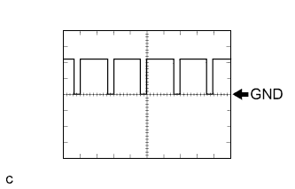
Item
Contents
Terminal
PMET - E1
Equipment Setting
5 V/DIV, 50 ms/DIV
Condition
Ignition switch ON
Waveform 2 (airbag deployment signal)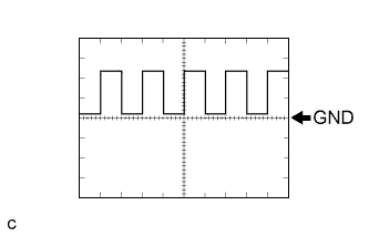
Item
Contents
Terminal
ABFS - E1
Equipment Setting
5 V/DIV, 500 ms/DIV
Condition
READY-on state
Waveform 3 (HV water pump signal)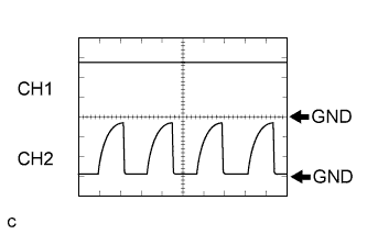
Item
Contents
Terminal
CH1: IWP - E1
CH2: NIWP - E1
Equipment Setting
5 V/DIV, 2 ms/DIV
Condition
READY-on state
Waveform 4 (vehicle speed signal)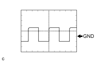
Item
Contents
Terminal
SPDI - E1
Equipment Setting
5 V/DIV, 20 ms/DIV
Condition
Driving at approximately 20 km/h (12 mph) in READY-on state
- HINT:
- The higher the vehicle speed, the shorter the cycle and higher the voltage.
Waveform 5 (immobilizer communication signal)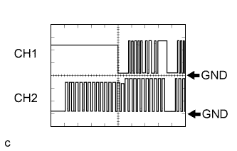
Item
Contents
Terminal
CH1: IMO - E1
CH2: IMI - E1
Equipment Setting
5 V/DIV, 200 ms/DIV
Condition
Ignition switch OFF → Ignition switch ON → READY-on state
Waveform 6 (system main relay operation signal)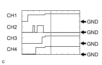
Item
Contents
Terminal
CH1: IGSW - E1
CH2: CON1 - E1
CH3: CON2 - E1
CH4: CON3 - E1
Equipment Setting
10 V/DIV, 500 ms/DIV
Condition
Ignition switch OFF → READY-on state
Waveform 7 (HV battery blower fan operation signal)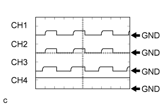
Item
Contents
Terminal
CH1: SI0 - E1
CH2: SI1 - E1
CH3: SI2 - E1
CH4: FCTL - E1
Equipment Setting
10 V/DIV, 200 ms/DIV
Condition
Ignition switch ON, during active test
Waveform 8 (Communication signal from battery to HV)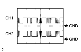
Item
Contents
Terminal
CH1: BTH+ - E1
CH2: BHT- - E1
Equipment Setting
2 V/DIV, 500 μs/DIV
Condition
Ignition switch ON
- HINT:
- The waveform varies depending on the contents of communication.
Waveform 9 (CAN communication signal)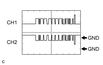
Item
Contents
Terminal
CH1: CANH - E1
CH2: CANL - E1
Equipment Setting
1 V/DIV, 20 ms/DIV
Condition
Ignition switch ON
- HINT:
- The waveform varies depending on the contents of communication.
Waveform 10 (Oil pump signal)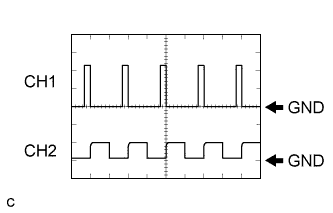
Item
Contents
Terminal
CH1: OPM1 - E1
CH2: OPMT - E1
Equipment Setting
5 V/DIV, 5 ms/DIV
Condition
READY-on state
Waveform 11 (radiator fan operation signal)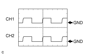
Item
Contents
Terminal
CH1: RFC1 - E1
CH2: RFC2 - E1
Equipment Setting
5 V/DIV, 1 ms/DIV
Condition
READY-on state with engine running
Waveform 12 (GO signal)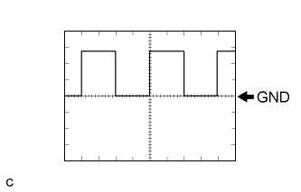
Item
Contents
Terminal
GO - E1
Equipment Setting
5 V/DIV, 20 ms/DIV
Condition
READY-on state with engine running
- HINT:
- The pulse cycle becomes shorter as the engine speed increases.
Waveform 13 (Crankshaft position signal)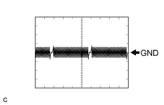
Item
Contents
Terminal
NE+ - NE-
Equipment Setting
5 V/DIV, 1 ms/DIV
Condition
READY-on state with engine running
- HINT:
- The pulse cycle becomes shorter as the engine speed increases.
Waveform 14 (engine speed signal)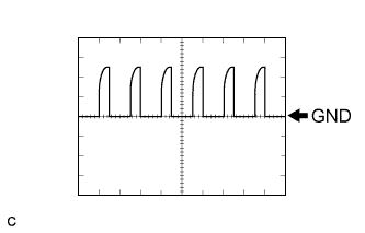
Item
Contents
Terminal
NEO - E1
Equipment Setting
10 V/DIV, 10 ms/DIV
Condition
READY-on state with engine running
- HINT:
- The pulse cycle becomes shorter as the engine speed increases.
Waveform 15 (communication signal from HV to MG)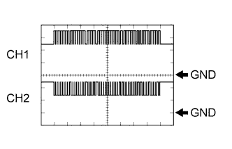
Item
Contents
Terminal
CH1: HTM+ - E1
CH2: HTM- - E1
Equipment Setting
1 V/DIV, 200 ms/DIV
Condition
READY-on state
- HINT:
- The waveform varies depending on the contents of communication.
Waveform 16 (MG communication clock signal)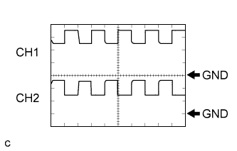
Item
Contents
Terminal
CH1: CLK+-E1
CH2: CLK--E1
Equipment Setting
1 V/DIV, 1 μs/DIV
Condition
READY-on state
Waveform 17 (MG communication request signal)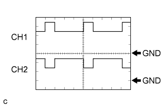
Item
Contents
Terminal
CH1: REQ+ - E1
CH2: REQ- - E1
Equipment Setting
1 V/DIV, 1 ms/DIV
Condition
READY-on state
Waveform 18 (communication signal from MG to HV)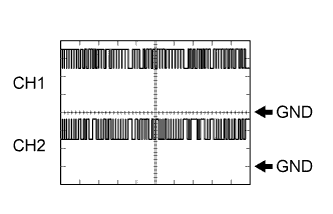
Item
Contents
Terminal
CH1: MTH+ - E1
CH2: MTH- - E1
Equipment Setting
1 V/DIV, 200 μs/DIV
Condition
READY-on state
- HINT:
- The waveform varies depending on the contents of communication.
Waveform 19 (A/C communication signal)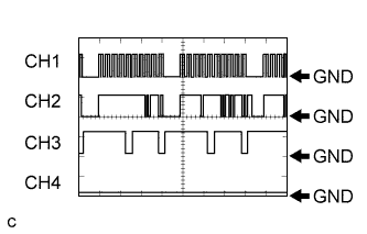
Item
Contents
Terminal
CH1: CLK - E1
CH2: ITE - E1
CH1: ETI - E1
CH2: STB- - E1
Equipment Setting
10 V/DIV, 100 ms/DIV
Condition
READY-on state with A/C stopped
- HINT:
- The waveform varies depending on the contents of communication.
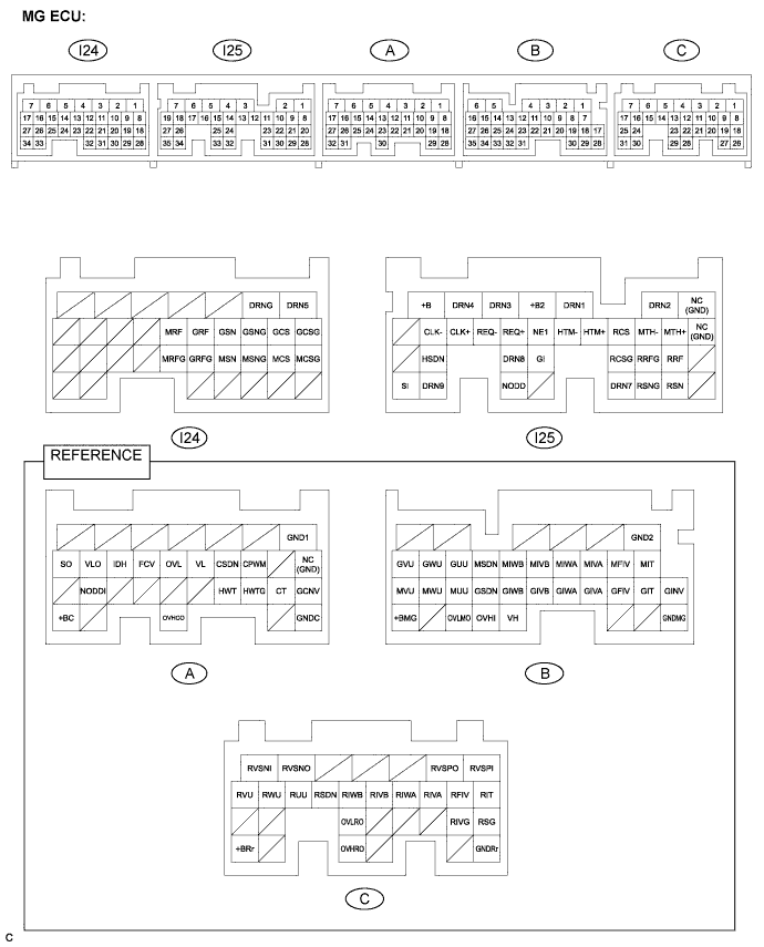
- HINT:
- Connectors A, B, and C are wired inside the w/ converter inverter assembly and usually not inspected. Terminal arrangement and measured values are provided as reference.
| Symbols (Terminal No.) |
Wiring Color |
Terminal Description |
Condition |
Standard voltage (V) |
| RVSPI (C-1) - RSG (C-18) |
- |
Power source for rear current sensor |
Ignition switch ON |
14.25 to 15.75 |
| RVSPO (C-2) - RSG (C-18) |
- |
Power source for rear current sensor |
Ignition switch ON |
14.25 to 15.75 |
| RVSNO (C-6) - RSG (C-18) |
- |
Power source for rear current sensor |
Ignition switch ON |
-15.9 to -14.1 |
| RVSNI (C-7) - RSG (C-18) |
- |
Power source for rear current sensor |
Ignition switch ON |
-15.9 to -14.1 |
| RIT (C-8) - RIVG (C-19) |
- |
Rear Motor inverter temperature |
Ignition switch ON |
1.5 to 4.5 |
| RFIV (C-9) - RIVG (C-19) |
- |
Rear Motor inverter fail signal |
Ignition switch ON, inverter operating normally |
5.5 to 7.5 |
| RFIV (C-9) - RIVG (C-19) |
- |
Rear Motor inverter fail signal |
Ignition switch ON, inverter not operating normally |
2 to 3 |
| RIVA (C-10) - RSG (C-18) |
- |
Rear Motor V phase current |
Ignition switch ON |
Approximately 0 |
| RIVB (C-12) - RSG (C-18) |
- |
Rear Motor V phase current |
Ignition switch ON |
Approximately 0 |
| RIWA (C-11) - RSG (C-18) |
- |
Rear Motor W phase current |
Ignition switch ON |
Approximately 0 |
| RIWB (C-13) - RSG (C-18) |
- |
Rear Motor W phase current |
Ignition switch ON |
Approximately 0 |
| RSDN (C-14) - RIVG (C-19) |
- |
Rear Motor shutdown signal |
Ignition switch ON, N position |
0.2 to 0.7 |
| RSDN (C-14) - RIVG (C-19) |
- |
Rear Motor shutdown signal |
Ignition switch ON, P position |
5.1 to 13.6 |
| RUU (C-15) - RIVG (C-19) |
- |
Rear Motor switch U signal |
Ignition switch ON |
Pulse generation (Waveform 1) |
| RWU (C-16) - RIVG (C-19) |
- |
Rear Motor switch W signal |
Ignition switch ON |
Pulse generation (Waveform 2) |
| RVU (C-17) - RIVG (C-19) |
- |
Rear Motor switch V signal |
Ignition switch ON |
Pulse generation (Waveform 3) |
| OVLMO (B-33) - GCNV (A-18) |
- |
Boost converter over-voltage signal |
Ignition switch ON, boost converter operating normally |
5.3 to 7.7 |
| OVLMO (B-33) - GCNV (A-18) |
- |
Boost converter over-voltage signal |
Ignition switch ON, boost converter not operating normally |
1.9 to 3.0 |
| OVHRO (C-19) - GINV (B-17) |
- |
Motor inverter over-voltage signal |
Ignition switch ON, inverter operating normally |
5.5 to 7.5 |
| OVHRO (C-19) - GINV (B-17) |
- |
Motor inverter over-voltage signal |
Ignition switch ON, inverter not operating normally |
2 to 3 |
| +BRr (C-31) - GNDRr (C-26) |
- |
Power source for rear inverter |
Ignition switch ON |
9 to 14 |
| MIT (B-7) - GINV (B-17) |
- |
Motor inverter temperature |
Ignition switch ON |
1.5 to 4.5 |
| MFIV (B-8) - GINV (B-17) |
- |
Motor inverter fail signal |
Ignition switch ON, inverter operating normally |
5.5 to 7.5 |
| MFIV (B-8) - GINV (B-17) |
- |
Motor inverter fail signal |
Ignition switch ON, inverter not operating normally |
2 to 3 |
| MIVA (B-9) - GINV (B-17) |
- |
Motor V phase current |
Ignition switch ON |
Approximately 0 |
| MIVB (B-11) - GINV (B-17) |
- |
Motor V phase current |
Ignition switch ON |
Approximately 0 |
| MIWA (B-10) - GINV (B-17) |
- |
Motor W phase current |
Ignition switch ON |
Approximately 0 |
| MIWB (B-12) - GINV (B-17) |
- |
Motor W phase current |
Ignition switch ON |
Approximately 0 |
| MSDN (B-13) - GINV (B-17) |
- |
Motor shutdown signal |
Ignition switch ON, N position |
0.2 to 0.7 |
| MSDN (B-13) - GINV (B-17) |
- |
Motor shutdown signal |
Ignition switch ON, P position |
5.1 to 13.6 |
| GUU (B-14) - GINV (B-17) |
- |
Generator switch U signal |
Ignition switch ON |
Pulse generation (Waveform 4) |
| GWU (B-15) - GINV (B-17) |
- |
Generator switch W signal |
Ignition switch ON |
Pulse generation (Waveform 5) |
| GVU (B-16) - GINV (B-17) |
- |
Generator switch V signal |
Ignition switch ON |
Pulse generation (Waveform 6) |
| GIT (B-18) - GINV (B-17) |
- |
Generator temperature sensor |
Ignition switch ON |
1.5 to 4.5 |
| GFIV (B-19) - GINV (B-17) |
- |
Generator fail signal |
Ignition switch ON, inverter operating normally |
5.5 to 7.5 |
| GFIV (B-19) - GINV (B-17) |
- |
Generator fail signal |
Ignition switch ON, inverter not operating normally |
2 to 3 |
| GIVA (B-20) - GINV (B-17) |
- |
Generator V phase current |
Ignition switch ON |
Approximately 0 |
| GIVB (B-22) - GINV (B-17) |
- |
Generator V phase current |
Ignition switch ON |
Approximately 0 |
| GIWA (B-21) - GINV (B-17) |
- |
Generator W phase current |
Ignition switch ON |
Approximately 0 |
| GIWB (B-23) - GINV (B-17) |
- |
Generator W phase current |
Ignition switch ON |
Approximately 0 |
| GSDN (B-24) - GINV (B-17) |
- |
Generator shutdown signal |
Ignition switch ON, N position |
0.2 to 0.7 |
| GSDN (B-24) - GINV (B-17) |
- |
Generator shutdown signal |
Ignition switch ON, P position |
5.1 to 13.6 |
| MUU (B-25) - GINV (B-17) |
- |
Motor switch U signal |
Ignition switch ON |
Pulse generation (Waveform 7) |
| MWU (B-26) - GINV (B-17) |
- |
Motor switch W signal |
Ignition switch ON |
Pulse generation (Waveform 8) |
| MVU (B-27) - GINV (B-17) |
- |
Motor switch V signal |
Ignition switch ON |
Pulse generation (Waveform 9) |
| VH (B-31) - GINV (B-17) |
- |
Inverter capacitor voltage monitor |
READY-on state |
1.6 to 3.8 |
| OVHI (B-32) - GINV (B-17) |
- |
Motor inverter over-voltage signal |
Ignition switch ON, inverter operating normally |
5.5 to 7.5 |
| OVHI (B-32) - GINV (B-17) |
- |
Motor inverter over-voltage signal |
Ignition switch ON, inverter not operating normally |
2 to -3 |
| +BMG (B-35) - GNDMG (B-28) |
- |
Power source for main inverter |
Ignition switch ON |
9 to 14 |
| CPWM (A-10) - GCNV (A-18) |
- |
Boost converter PWM switch signal |
READY-on state, parking brake on, D position, brake and accelerator pedal depressed |
Pulse generation* |
| CSDN (A-11) - GCNV (A-18) |
- |
Boost converter shutdown signal |
Ignition switch ON |
5.6 or higher |
| VL (A-12) - GCNV (A-18) |
- |
Boost converter input voltage |
READY-on state |
2.6 to 4.3 |
| OVL (A-13) - GCNV (A-18) |
- |
Boost converter over-voltage signal |
Ignition switch ON, boost converter operating normally |
5.3 to 7.7 |
| OVL (A-13) - GCNV (A-18) |
- |
Boost converter over-voltage signal |
Ignition switch ON, boost converter not operating normally |
1.9 to 3.0 |
| FCV (A-14) - GCNV (A-18) |
- |
Boost converter fail signal |
Ignition switch ON, boost converter operating normally |
5.3 to 7.7 |
| FCV (A-14) - GCNV (A-18) |
- |
Boost converter fail signal |
Ignition switch ON, boost converter not operating normally |
1.9 to 3.0 |
| IDH (A-15) - GND1 (A-1) |
- |
Blower Motor for A/C operation inhibition request signal |
Ignition switch ON, permission for blower Motor operation requested |
5 to 7 |
| IDH (A-15) - GND1 (A-1) |
- |
Blower Motor for A/C operation inhibition request signal |
Ignition switch ON, blower Motor operation inhibition requested |
2 to 4 |
| VLO (A-16) - GND1 (A-1) |
- |
DC/DC converter voltage switch signal |
Ignition switch ON |
Pulse generation (Waveform 10) |
| SO (A-17) - GND1 (A-1) |
- |
Auxiliary battery voltage monitor |
Ignition switch ON |
9 to 14 |
| CT (A-19) - GCNV (A-18) |
- |
Boost converter temperature sensor |
Ignition switch ON |
1.5 to 4.5 |
| HWT (A-21) - HWTG (A-20) |
- |
Inverter coolant temperature sensor |
Ignition switch ON |
0.5 to 4.8 |
| NODDI (A-26) - GND1 (A-1) |
- |
DC/DC converter operation monitor/stop request signal |
DC/DC converter operating normally |
5.3 to 6.7 |
| NODDI (A-26) - GND1 (A-1) |
- |
DC/DC converter operation monitor/stop request signal |
DC/DC converter not operating normally |
2.5 to 3.5 |
| NODDI (A-26) - GND1 (A-1) |
- |
DC/DC converter operation monitor/stop request signal |
DC/DC converter ordered to stop |
0.1 to 0.8 |
| OVHCO (A-30) - GINV (A-18) |
- |
Motor inverter over-voltage signal |
Ignition switch ON, inverter operating normally |
5.5 to 7.5 |
| OVHCO (A-30) - GINV (A-18) |
- |
Motor inverter over-voltage signal |
Ignition switch ON, inverter not operating normally |
2 to 3 |
| +BC (A-32) - GNDC (A-28) |
- |
Power source for boost converter |
Ignition switch ON |
9 to 14 |
| +B2 (I25-4) - GND1 (A-1) |
R |
MG ECU power source |
Ignition switch ON |
9 to 14 |
| +B (I25-7) - GND1 (A-1) |
R |
MG ECU power source |
Ignition switch ON |
9 to 14 |
| MTH+ (I25-9) - GND1 (A-1) |
B |
Communication signal from MG to HV |
Ignition switch ON |
Pulse generation (Waveform 11) |
| MTH- (I25-10) - GND1 (A-1) |
W |
Communication signal from MG to HV |
Ignition switch ON |
Pulse generation (Waveform 11) |
| HTM+ (I25-12) - GND1 (A-1) |
B |
Communication signal from HV to MG |
Ignition switch ON |
Pulse generation (Waveform 12) |
| HTM- (I25-13) - GND1 (A-1) |
W |
Communication signal from HV to MG |
Ignition switch ON |
Pulse generation (Waveform 12) |
| NEI (I25-14) - GND1 (A-1) |
B |
Engine speed signal |
READY-on state with engine running |
Pulse generation* |
| REQ+ (I25-15) - GND1 (A-1) |
B |
Communication request signal |
Ignition switch ON |
Pulse generation (Waveform 13) |
| REQ- (I25-16) - GND1 (A-1) |
W |
Communication request signal |
Ignition switch ON |
Pulse generation (Waveform 13) |
| CLK+(I25-17) - GND1 (A-1) |
B |
Communication clock signal |
Ignition switch ON |
Pulse generation (Waveform 14) |
| CLK- (I25-18) - GND1 (A-1) |
W |
Communication clock signal |
Ignition switch ON |
Pulse generation (Waveform 14) |
| RRF (I25-21) - RRFG (I25-22) |
BR - G |
Rear Motor resolver signal |
Rear Motor resolver stopped or running |
Pulse generation (Waveform 15) |
| RSN (I25-29) - RSNG (I25-30) |
O - R |
Rear Motor resolver signal |
Rear Motor resolver stopped or running |
Pulse generation (Waveform 15) |
| RCS (I25-11) - RCSG (I25-23) |
W-G - Y |
Rear Motor resolver signal |
Rear Motor resolver stopped or running |
Pulse generation (Waveform 15) |
| GI (I25-24) - GND1 (A-1) |
W |
GI signal |
READY-on state with engine running |
Pulse generation* |
| HSDN (I25-26) - GINV (B-17) |
B |
Emergency shutdown signal |
Ignition switch ON |
Below 0.5 |
| NODD (I25-33) - GND1 (A-1) |
W |
DC/DC converter operation monitor/stop request signal |
DC/DC converter operating normally |
5.3 to 6.7 |
| NODD (I25-33) - GND1 (A-1) |
W |
DC/DC converter operation monitor/stop request signal |
DC/DC converter not operating normally |
2.5 to 3.5 |
| NODD (I25-33) - GND1 (A-1) |
W |
DC/DC converter operation monitor/stop request signal |
DC/DC converter ordered to stop |
0.1 to 0.8 |
| SI (I25-35) - GND1 (A-1) |
B |
Auxiliary battery voltage monitor |
Ignition switch ON |
9 to 14 |
| GRF (I24-12) - GRFG (I24-22) |
BR - G |
Generator resolver signal |
Generator resolver stopped or running |
Pulse generation (Waveform 16) |
| GSN (I24-11) - GSNG (I24-10) |
L - R |
Generator resolver signal |
Generator resolver stopped or running |
Pulse generation (Waveform 16) |
| GCS (I24-9) - GCSG (I24-8) |
W - Y |
Generator resolver signal |
Generator resolver stopped or running |
Pulse generation (Waveform 16) |
| MRF (I24-13) - MRFG (I24-23) |
BR - G |
Motor resolver signal |
Motor resolver stopped or running |
Pulse generation (Waveform 17) |
| MSN (I24-21) - MSNG (I24-20) |
L - R |
Motor resolver signal |
Motor resolver stopped or running |
Pulse generation (Waveform 17) |
| MCS (I24-19) - MCSG (I24-18) |
W - Y |
Motor resolver signal |
Motor resolver stopped or running |
Pulse generation (Waveform 17) |
| Oscilloscope waveforms |
- HINT:
- Oscilloscope waveform samples are provided here for informational purposes. Noise and fluttering waveforms have been omitted.
Waveform 1 (Rear Motor switch U signal)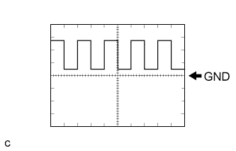
Item
Contents
Terminal
RUU - RIVG
Equipment Setting
5 V/DIV, 100 μs/DIV
Condition
Ignition switch ON
Waveform 2 (Rear Motor switch W signal)
Item
Contents
Terminal
RWU - RIVG
Equipment Setting
5 V/DIV, 100 μs/DIV
Condition
Ignition switch ON
Waveform 3 (Rear Motor switch V signal)
Item
Contents
Terminal
RVU - RIVG
Equipment Setting
5 V/DIV, 100 μs/DIV
Condition
Ignition switch ON
Waveform 4 (Generator switch U signal)
Item
Contents
Terminal
GUU - GINV
Equipment Setting
5 V/DIV, 100 μs/DIV
Condition
Ignition switch ON
Waveform 5 (Generator switch W signal)
Item
Contents
Terminal
GWU - GINV
Equipment Setting
5 V/DIV, 100 μs/DIV
Condition
Ignition switch ON
Waveform 6 (Generator switch V signal)
Item
Contents
Terminal
GVU - GINV
Equipment Setting
5 V/DIV, 100 μs/DIV
Condition
Ignition switch ON
Waveform 7 (Motor switch U signal)
Item
Contents
Terminal
MUU - GINV
Equipment Setting
5 V/DIV, 100 μs/DIV
Condition
Ignition switch ON
Waveform 8 (Motor switch W signal)
Item
Contents
Terminal
MWU - GINV
Equipment Setting
5 V/DIV, 100 μs/DIV
Condition
Ignition switch ON
Waveform 9 (Motor switch V signal)
Item
Contents
Terminal
MVU - GINV
Equipment Setting
5 V/DIV, 100 μs/DIV
Condition
Ignition switch ON
Waveform 10 (DC/DC converter voltage switch signal)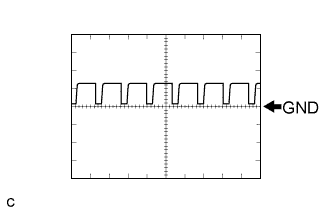
Item
Contents
Terminal
VLO - GND1
Equipment Setting
5 V/DIV, 100 μs/DIV
Condition
Ignition switch ON
Waveform 11 (communication signal from MG to HV)
Item
Contents
Terminal
CH1: MTH+ - GND1
CH2: MTH- - GND1
Equipment Setting
1 V/DIV, 200 μs/DIV
Condition
Ignition switch ON
- HINT:
- The waveform varies depending on the contents of communication.
Waveform 12 (communication signal from HV to MG)
Item
Contents
Terminal
CH1: HTM+ - GND1
CH2: HTM- - GND1
Equipment Setting
1 V/DIV, 200 ms/DIV
Condition
Ignition switch ON
- HINT:
- The waveform varies depending on the contents of communication.
Waveform 13 (MG communication request signal)
Item
Contents
Terminal
CH1: REQ+ - GND1
CH2: REQ- - GND11
Equipment Setting
1 V/DIV, 1 ms/DIV
Condition
Ignition switch ON
Waveform 14 (MG communication clock signal)
Item
Contents
Terminal
CH1: CLK+ - GND1
CH2: CLK- - GND1
Equipment Setting
1 V/DIV, 1 μs/DIV
Condition
Ignition switch ON
Waveform 15 (Rear Motor resolver signal)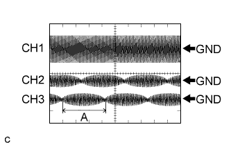
Item
Contents
Terminal
CH1: RRF - RRFG
CH2: RSN - RSNG
CH2: RCS - RCSG
Equipment Setting
CH1: 10 V/DIV, 1 ms/DIV
CH2, CH3: 5 V/DIV, 1 ms/DIV
Condition
Resolver running
- HINT:
- Pulse cycle A becomes shorter as the rotor speed increases.
Waveform 16 (Generator resolver signal)
Item
Contents
Terminal
CH1: GRF - GRFG
CH2: GSN - GSNG
CH2: GCS - GCSG
Equipment Setting
CH1: 10 V/DIV, 1 ms/DIV
CH2, CH3: 5 V/DIV, 1 ms/DIV
Condition
Resolver running
- HINT:
- Pulse cycle A becomes shorter as the rotor speed increases.
Waveform 17 (Motor resolver signal)
Item
Contents
Terminal
CH1: MRF - MRFG
CH2: MSN - MSNG
CH2: MCS - MCSG
Equipment Setting
CH1: 10 V/DIV, 1 ms/DIV
CH2, CH3: 5 V/DIV, 1 ms/DIV
Condition
Resolver running
- HINT:
- Pulse cycle A becomes shorter as the rotor speed increases.