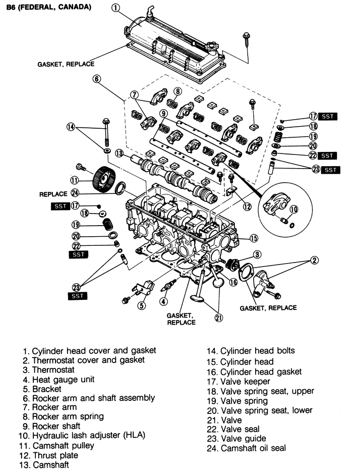
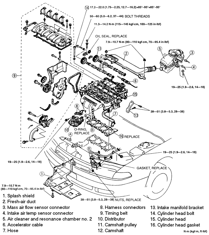
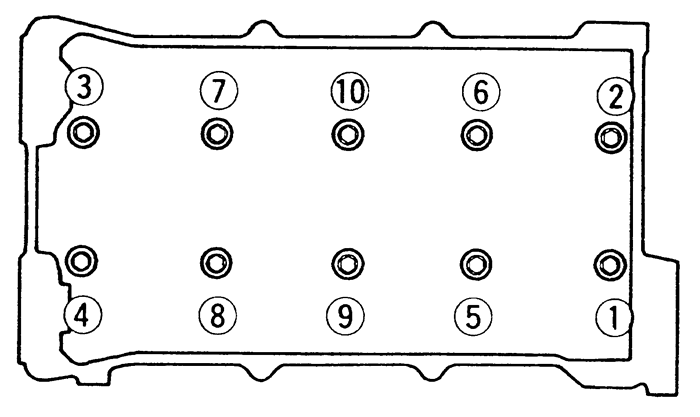
| Fig. 1: Cylinder head components -- 1993-94 323 1.6L
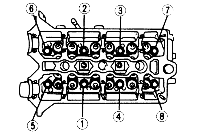
(B6E) engines
|
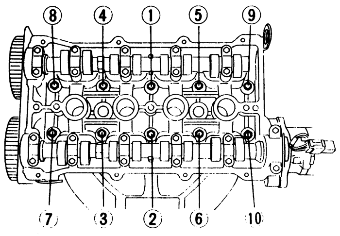
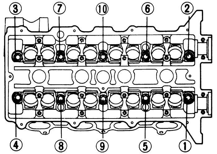
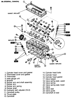
| Fig. 2: Cylinder head torque sequence -- 1993-94
323 and Protege
|
CAUTION
When draining the coolant, keep in mind that cats and dogs are attracted
by the ethylene glycol antifreeze, and are quite likely to drink any that
is left in an uncovered container or in puddles on the ground. This will
prove fatal in sufficient quantity. Always drain the coolant into a sealable
container. Coolant should be reused unless it is contaminated or several
years old.
- Disconnect the negative battery cable and remove
the engine undercover.
- Remove the air ducts from the air cleaner and throttle
body.
- Tag and disconnect the spark plug wires from the
spark plugs. Remove the spark plugs and the distributor cap and wires
assembly. Remove the distributor.
- Drain the cooling system and disconnect the radiator
and heater hoses.
- Disconnect the exhaust pipe and remove the exhaust
manifold.
- On DOHC engines, remove the coolant bypass pipe.
- Disconnect the accelerator cable.
- Label and disconnect all necessary electrical connections
and vacuum hoses. Disconnect the fuel lines.
- Remove the intake manifold bracket and the intake
manifold.
- Remove the cylinder head cover bolts and the cylinder
head cover.
- Remove the timing belt cover(s). Rotate the crankshaft,
in the normal direction of rotation, until the No. 1 cylinder piston is
at TDC on the compression stroke. Make sure the timing marks on the crankshaft
and camshaft sprocket(s) are properly aligned and mark the direction of
rotation of the belt.
- Loosen the timing belt tensioner and remove the belt.
Do not rotate the crankshaft until the timing belt is reinstalled.
-
When everything is disconnected, loosen the cylinder head bolts in
the reverse of the tightening sequence. Remove the bolts and lift the
head off the engine.
To install:
- Thoroughly, clean the cylinder head and the block
contact surfaces. Examine the head gasket and check the cylinder head
for cracks. Check the cylinder head for warpage using a feeler gauge and
straightedge. The maximum allowable distortion is 0.004 in. (0.10mm) on
1.8L engine.
- Clean the cylinder head bolts and the threads in
the block. Make sure the bolts turn freely in the block.
- Install a new head gasket on the engine block. Make
sure the camshaft sprocket timing marks are still aligned, as set during
the removal procedure. Install the cylinder head.
- Lubricate the bolt threads and seat surfaces with
clean engine oil and install them. Torque the bolts in 2-3 steps to 56-60
ft. lbs. (75-81 Nm) in the proper sequence.
- Make sure the crankshaft and camshaft sprocket timing
marks are aligned, install the timing belt and set the tension. Carefully
rotate the crankshaft 2 turns to make sure the timing marks still line
up.
- Apply a thin bead of sealant to the cylinder head
cover and install the new gasket. Install the cover and torque the cover
bolts to 78 inch lbs. (9 Nm).
- Install the timing belt cover(s) and tighten the
bolts to 95 inch lbs. (11 Nm).
- Use new gaskets and install the manifolds. Torque
the intake manifold bolts/nuts to 19 ft. lbs. (25 Nm) and install the
intake manifold bracket. Torque the exhaust manifold nuts to 34 ft. lbs.
(46 Nm).
- Use a new gasket to connect the exhaust pipe and
torque the nuts to 34 ft. lbs. (46 Nm).
- If removed, install the radiator and connect all
cooling system hoses. On DOHC engines, install the coolant bypass pipe.
- Install the distributor, spark plugs, distributor
cap and wires.
- Connect all vacuum and fuel system hoses and connect
all wiring.
- Connect the accelerator cable and install the air
ducts and engine undercover.
- Connect the negative battery cable. Fill and bleed
the cooling system. Change the engine oil.
- Start the engine and bring to normal operating temperature.
Check for leaks. Check the ignition timing and idle speed.
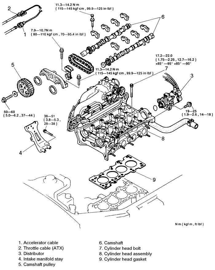
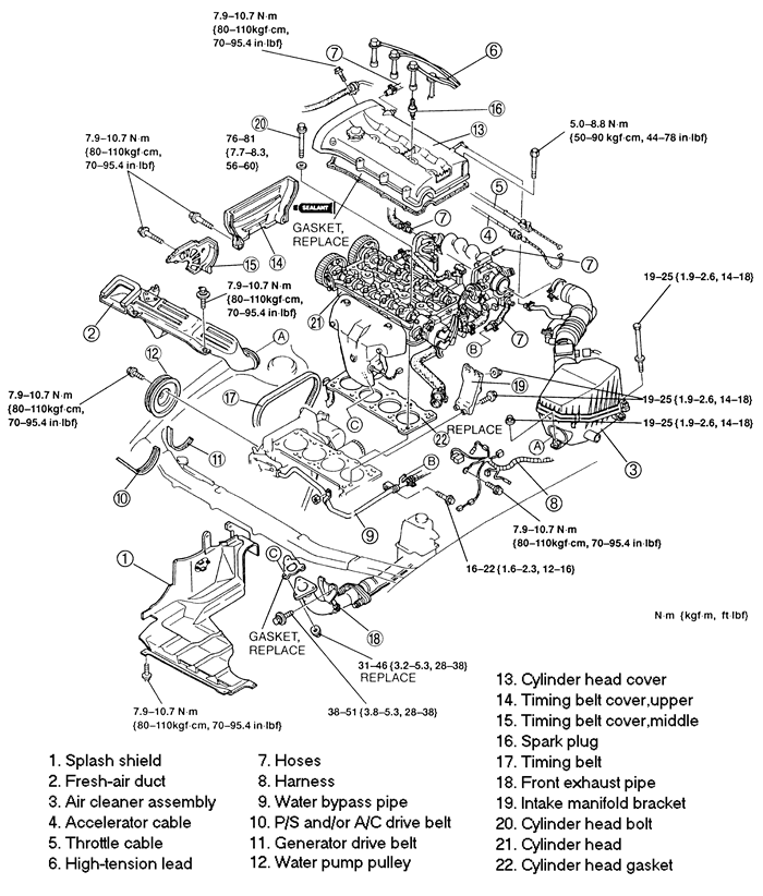
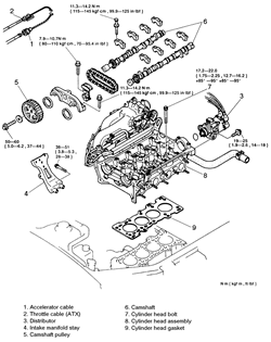
| Fig. 3: Cylinder head assembly (exploded view) --
1995-97 Protege 1.5L (Z5D) engines
|
- Relieve the fuel system pressure and disconnect the
negative battery cable. Drain the cooling system.
- Raise and safely support the vehicle.
- Remove the right front wheel and splash shield.
- Remove the power steering belt shield. Loosen the
power steering adjusting bolt, lockbolt and through-bolt and remove the
power steering belt.
- Loosen the alternator adjusting bolt and upper mounting
bolt. Remove the alternator belt.
- Remove the water pump pulley.
- Using a holder tool, hold the crankshaft pulley and
remove the pulley bolt. Use a suitable puller to remove the pulley, then
remove the guide plate.
- Remove the power steering hose brackets from the
cylinder head cover. Label and disconnect the spark plug wires and wire
clips.
- Disconnect the breather tube and PCV valve from the
cylinder head cover. Remove the bolts, in 2 steps, in the reverse order
of the tightening sequence. Remove the cylinder head cover.
- Remove the oil dipstick and bracket.
- Remove the timing belt upper cover.
- Use a suitable engine support tool, and remove the
number three engine mount bracket.
- Remove the timing belt middle and lower covers.
- Rotate the crankshaft, in the normal direction of
rotation, until the No. 1 cylinder piston is at TDC on the compression
stroke. Make sure the timing marks on the crankshaft and camshaft sprocket(s)
are properly aligned and mark the direction of rotation of the belt.
-
Loosen the timing belt tensioner and remove the belt. Do not rotate
the crankshaft until the timing belt is reinstalled.
| Fig. 4: Cylinder head assembly (exploded view) --
1995-97 Protege 1.5L (Z5D) engines
|
- Remove air cleaner assembly and front pipe.
- Remove the exhaust manifold.
- Disconnect the accelerator and throttle cables.
- Tag and disconnect the spark plug wires from the
spark plugs. Remove the spark plugs and the distributor cap and wires
assembly. Remove the distributor.
- Disconnect the following hoses: Heater, brake vacuum,
purge, fuel, water and upper radiator.
- Label and disconnect the distributor/coil connectors,
engine coolant temperature sensor connector, cooling fan coolant temperature
sensor connector, and temperature gauge sensor connector.
- Remove the camshaft sprockets and the camshaft.
- On the 1.5L engine, remove the tappets. Identify
each tappet as it is removed so it can be reinstalled in the same position.
-
On the 1.8L engine, remove the hydraulic lifters. Identify each lifter
as it is removed so it can be reinstalled in the same position. If the
lifters are to be reused, store them upside down in an oil-filled sealed
container.
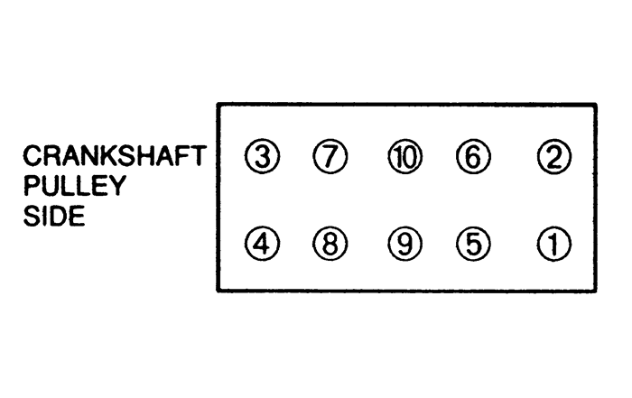
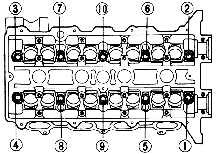
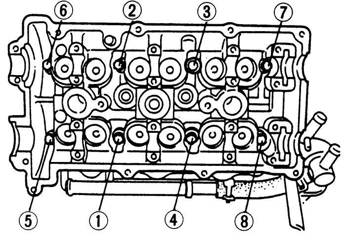
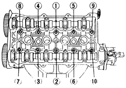
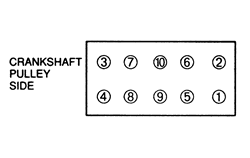
| Fig. 5: Cylinder head bolt (loosening sequence; tighten
in reverse order) -- 1995-97 Protege 1.8L (BPD) and 1.5L (Z5D) engines
|
- Remove the intake manifold bracket and the intake
manifold.
-
Loosen the cylinder head bolts, in 2-3 steps, in sequence. Remove the
bolts and the cylinder head.
To install:
- Thoroughly, clean the cylinder head and the block
contact surfaces. Examine the head gasket and check the cylinder head
for cracks. Check the cylinder head for warpage using a feeler gauge and
straightedge. The maximum allowable distortion is 0.004 in. (0.10mm).
- Clean the cylinder head bolts and the threads in
the block. Make sure the bolts turn freely in the block.
- Install a new head gasket on the engine block. Make
sure the camshaft sprocket timing marks are still aligned, as set during
the removal procedure. Install the cylinder head.
-
Lubricate the bolt threads and seat surfaces with clean engine oil
and install them as follows;
- On the 1.5L (Z5D) engines, torque the bolts in
2-3 steps to 13-16 ft. lbs. (17-22 Nm) in the proper sequence. Paint a
reference mark on each bolt head and turn the bolts, in sequence, 90°,
and then an additional 90°.
- On the 1.8L (BPD) engines, torque the bolts in
2-3 steps to 56-60 ft. lbs. (75-81 Nm) in the proper sequence.
- Use new gaskets and install the manifolds. Torque
the intake manifold bolts/nuts to 19 ft. lbs. (25 Nm) and install the
intake manifold bracket. Torque the exhaust manifold nuts to 34 ft. lbs.
(46 Nm).
- Use a new gasket to connect the exhaust pipe and
torque the nuts to 34 ft. lbs. (46 Nm).
- Apply clean engine oil to the tappets and install
them in their original positions.
- Install the camshaft and sprockets.
- Make sure the crankshaft and camshaft sprocket timing
marks are aligned, install the timing belt and set the tension. Carefully
rotate the crankshaft 2 turns to make sure the timing marks still line
up.
- Install the timing belt middle and lower covers,
and tighten the bolts to 70-95 inch lbs. (8-11 Nm).
- Install the number three engine mount bracket. Tighten
the nut to 70-95 inch lbs. (8-11 Nm), and the bolt to 14-16 ft. lbs. (19-22
Nm). Remove the engine support tool.
- Install the upper timing belt cover and tighten the
bolts to 70-95 inch lbs. (8-11 Nm).
- Install the oil dipstick and bracket.
- Apply silicone sealant to the cylinder surface in
the area adjacent to the front camshaft bearing caps. Apply sealant to
a new gasket and install it on the cylinder head cover.
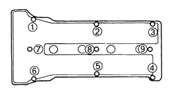
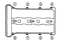
- Install the cylinder head cover and tighten the bolts
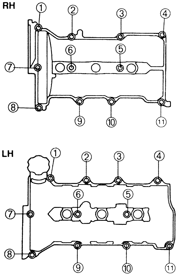
in 5-6 steps, in sequence, to 61-95 inch lbs. (7-11 Nm) on the 1.5 (Z5D)
engines and 44-78 inch lbs. (5-9 Nm) on the 1.8L (BPD) engines.
- Install the power steering hose brackets and tighten
the bolts to 70-95 inch lbs. (7-11 Nm). Connect the spark plug wires and
wire clips. Connect the breather tube and PCV valve.
- Install the guide plate, crankshaft pulley and pulley
bolt. Hold the pulley with the holder tool and tighten the bolt to 116-122
ft. lbs. (157-166 Nm).
- Install the water pump pulley.
- Install the alternator belt and adjust the tension.
- Install the power steering belt and adjust the tension.
Tighten the through-bolt to 32-44 ft. lbs. (44-60 Nm) and the lockbolt
to 24-33 ft. lbs. (32-46 Nm). Install the power steering belt shield and
tighten the bolts to 86 inch lbs. (9 Nm).
- Install the splash shield and wheel. Lower the vehicle.
- Connect the electrical engine harness connectors.
- Connect the heater, brake vacuum, purge, fuel, water
and upper radiator hoses.
- Install the distributor, spark plugs, distributor
cap and wires.
- Connect and adjust the accelerator and throttle cables.
- Install the cleaner.
- Connect the negative battery cable. Fill and bleed
the cooling system. Change the engine oil.
- Adjust the ignition timing.
-
Start the engine and bring to normal operating temperature. Check for
leaks. Check the ignition timing and idle speed.
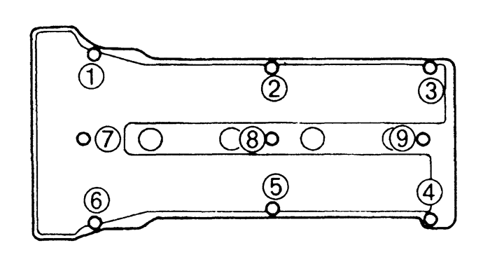
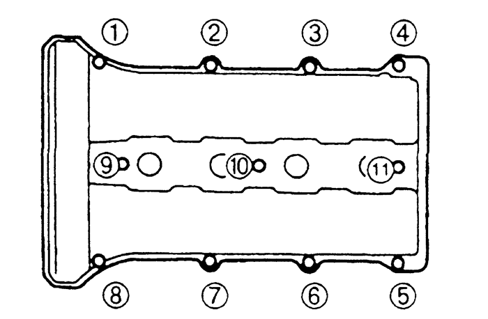
| Fig. 6: Cylinder head cover (bolt tightening sequence) --
1995-97 Protege 1.5L (Z5D) engines
|
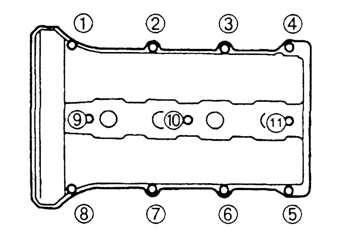
| Fig. 7: Cylinder head cover (bolt tightening sequence) --
1995-97 Protege 1.8L (BPD) engines
|
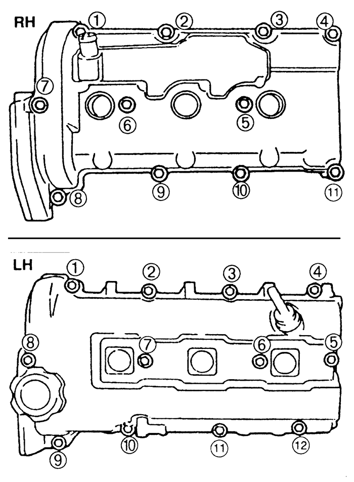
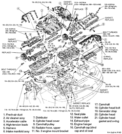
| Fig. 8: Exploded view of the cylinder head assembly --
1993-95 MX3 1.8L (K8), 626 and MX6 2.5L (KL) engines
|
- Relieve the fuel system pressure and disconnect the
negative battery cable. Drain the cooling system.
- Remove the fresh air duct and the air cleaner assembly.
- If additional clearance space is needed, remove the
battery.
- Disconnect the accelerator cable.
- Disconnect the wiring harness from the cylinder heads.
- Disconnect the fuel, heater and vacuum hoses.
- Remove the intake manifold.
- Remove the distributor.
- Disconnect the ventilation pipe from the left cylinder
head cover, remove the bolts and remove the cylinder head covers.
- Remove the timing belt covers and the timing belt.
- Remove the camshafts. Remove the 3 bolts and the
seal plate from the front of the engine.
- Remove the upper radiator hose. Raise and safely
support the vehicle.
- Disconnect the oxygen sensor connectors. Remove the
exhaust pipe-to-manifold nuts and lower the exhaust pipes. Lower the vehicle.
- Remove the hydraulic lifters. Identify each lifter
as it is removed so it can be reinstalled in the same position. If the
lifters are to be reused, store them upside down in an oil-filled, sealed
container.
- Loosen the cylinder head bolts, in 2-3 steps, in
the reverse order of the torque sequence. Remove the bolts and remove
the cylinder heads.
-
Clean all gasket mating surfaces. Inspect the cylinder head for damage,
cracks, and water and oil leakage. Check the head gasket surface for distortion
using a straight-edge and feeler gauge. Maximum allowable distortion is
0.004 in. (0.10mm).
To install:
- Position NEW head gaskets on the cylinder block.
The gaskets cannot be interchanged between sides and are marked R and
L for right and left side.
-
Install the cylinder heads. Apply clean engine oil to the threads of
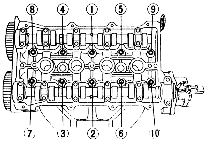
new cylinder head bolts and install. Tighten the cylinder head bolts in
2-3 steps, in sequence, to 17-19 ft. lbs. (23-26 Nm).
| Fig. 9: Cylinder head bolt (tightening sequence) --
1993-95 MX3 1.8L (K8), 1993-97 626 and MX6 2.5L (KL) engines
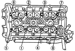
|
- Paint a mark on the edge of each cylinder head bolt
to use as a reference. Turn each bolt, in sequence, 90 degrees. Again,
turn each bolt, in sequence, an additional 90 degrees.
- Apply clean engine oil to the hydraulic lifters and
install them in their original positions. Make sure they move freely in
the bores.
- Install the camshafts. Raise and safely support the
vehicle.
- Connect the exhaust pipes to the manifolds and tighten
the nuts to 41 ft. lbs. (55 Nm). Connect the oxygen sensor connectors.
Lower the vehicle.
- Install the timing belt and timing belt covers.
-
Apply sealant to the cylinder head surface in the area of the front
and rear camshaft caps. Install new gaskets and install the cylinder head
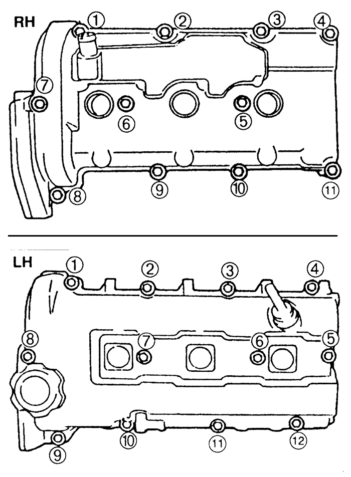
covers. Tighten the bolts in 5-6 steps, in sequence, to 44-78 inch lbs.
(5-9 Nm).
| Fig. 10: Cylinder head cover (tightening sequence) --
1993-95 MX3 1.8L (K8), 1993-97 626 and MX6 2.5L (KL) engines
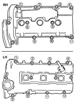
|
- Install the intake manifold using new gaskets. Tighten
the mounting bolts to 14-18 ft. lbs. (19-25 Nm).
-
Install the distributor:
- Apply clean engine oil to a new O-ring, and position
it on the distributor.
- Apply clean engine oil to the drive blade. Install
the distributor with the blade fit into the camshaft groove.
- Hand tighten the mounting bolts.
- Connect the vacuum, heater and fuel hoses.
- Connect the wiring harness to the cylinder heads.
- Connect and adjust the accelerator cable.
- If removed, install the battery.
- Install the air cleaner assembly and the fresh air
duct.
- Connect the negative battery cable. Fill and bleed
the cooling system. Adjust the ignition timing and idle speed. Run the
engine and check for proper operation.
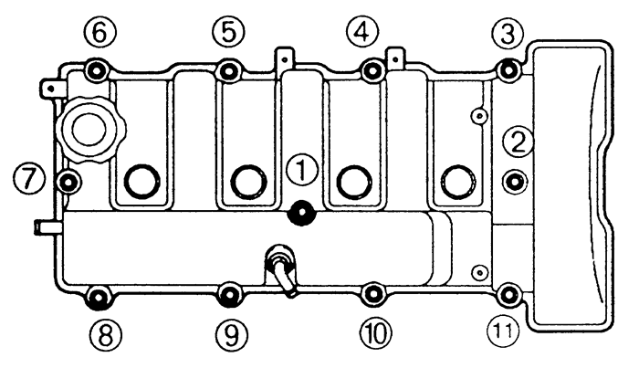
| Fig. 11: Exploded view of the cylinder head assembly --
1994-95 MX3 1.6L (B6-ZE) engines
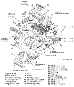
|
- Relieve the fuel system pressure and disconnect the
negative battery cable. Drain the cooling system.
- Remove the splash shield, fresh air duct and air
cleaner assembly.
- Disconnect the accelerator and throttle cables.
- Tag and disconnect the spark plug wires from the
spark plugs. Remove the spark plugs and the distributor cap and wires
assembly. Remove the distributor.
- Disconnect the following hoses: Heater, brake vacuum,
purge, fuel, water and upper radiator.
- Label and disconnect the distributor/coil connectors,
engine coolant temperature sensor connector, cooling fan coolant temperature
sensor connector and temperature gauge sensor connector.
- Remove the coolant bypass pipe.
- Remove the accessory drive belts. Remove the power
steering pump bolts and secure the pump aside with mechanics wire, leaving
the hoses attached.
- Remove the water pump pulley.
- Remove the alternator bracket nut and bolt and position
the bracket aside.
- Disconnect the hoses from the cylinder head cover
and loosen the cover bolts in 5-6 step sequences. Remove the cylinder
head cover.
- Remove the timing belt cover(s). Rotate the crankshaft,
in the normal direction of rotation, until the No. 1 cylinder piston is
at TDC on the compression stroke. Make sure the timing marks on the crankshaft
and camshaft sprocket(s) are properly aligned and mark the direction of
rotation of the belt.
- Loosen the timing belt tensioner and remove the belt.
Do not rotate the crankshaft until the timing belt is reinstalled.
- Remove the camshaft sprockets and the camshaft.
- Remove the hydraulic lifters. Identify each lifter
as it is removed so it can be reinstalled in the same position. If the
lifters are to be reused, store them upside down in an oil-filled sealed
container.
- Disconnect the exhaust pipe and remove the exhaust
manifold.
- Remove the intake manifold bracket and the intake
manifold.
-
Loosen the cylinder head bolts, in 2-3 steps, in sequence. Remove the
bolts and the cylinder head.
| Fig. 12:Cylinder head bolt (loosening sequence; tighten
in reverse order) -- 1994-95 MX3 1.6L (B6-ZE) engines
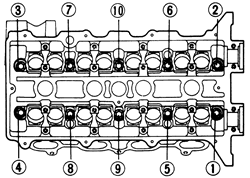
|
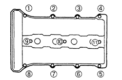
| Fig. 13:Cylinder head cover (bolt tightening sequence) --
1994-95 MX3 1.6L (B6-ZE) engines
|
To install:
- Thoroughly, clean the cylinder head and the block
contact surfaces. Examine the head gasket and check the cylinder head
for cracks. Check the cylinder head for warpage using a feeler gauge and
straightedge. The maximum allowable distortion is 0.004 in. (0.10mm).
- Clean the cylinder head bolts and the threads in
the block. Make sure the bolts turn freely in the block.
- Install a new head gasket on the engine block. Make
sure the camshaft sprocket timing marks are still aligned, as set during
the removal procedure. Install the cylinder head.
- Lubricate the bolt threads and seat surfaces with
clean engine oil and install them. Torque the bolts in 2-3 steps to 56-60
ft. lbs. (75-81 Nm) in the proper sequence.
- Use new gaskets and install the manifolds. Torque
the intake manifold bolts/nuts to 19 ft. lbs. (25 Nm) and install the
intake manifold bracket. Torque the exhaust manifold nuts to 34 ft. lbs.
(46 Nm).
- Use a new gasket to connect the exhaust pipe and
torque the nuts to 34 ft. lbs. (46 Nm).
- Apply clean engine oil to the hydraulic lifters and
install them in their original positions. Make sure they move freely in
the bores.
- Install the camshaft and sprockets.
- Make sure the crankshaft and camshaft sprocket timing
marks are aligned, install the timing belt and set the tension. Carefully
rotate the crankshaft 2 turns to make sure the timing marks still line
up.
- Apply a thin bead of sealant to the cylinder head
cover and install the new gasket. Install the cover and torque the cover
bolts to 78 inch lbs. (9 Nm).
- Install the timing belt cover(s) and tighten the
bolts to 95 inch lbs. (11 Nm).
- Install the alternator bracket. Tighten the bracket
nut and bolt to 19 ft. lbs. (25 Nm).
- Install the water pump pulley.
- Install the alternator belt and adjust the tension.
- Loosely install the power steering pump through and
lockbolts. Connect the pump pressure switch connector.
- Install the power steering pump belt and adjust the
tension. Tighten the pump through-bolt to 45 ft. lbs. (61 Nm) and the
lockbolt to 34 ft. lbs. (46 Nm).
- Install the power steering pump belt shield and tighten
the bolts to 86 inch lbs. (9 Nm). Install the power steering hose brackets
to the cylinder head cover, and tighten the bolts to 88 inch lbs. (10
Nm).
- Install the coolant bypass pipe.
- Connect the electrical engine harness connectors.
- Connect the heater, brake vacuum, purge, fuel, water
and upper radiator hoses.
- Install the distributor, spark plugs, distributor
cap and wires.
- Connect and adjust the accelerator and throttle cables.
- Install the air ducts, cleaner and splash shield.
- Connect the negative battery cable. Fill and bleed
the cooling system. Change the engine oil.
- Adjust the ignition timing.
- Start the engine and bring to normal operating temperature.
Check for leaks. Check the ignition timing and idle speed.
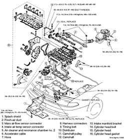
| Fig. 14: Exploded view of the cylinder head assembly --
626 and MX6 2.0L (FS) engine
|
- Relieve the fuel system pressure and disconnect the
negative battery cable. Drain the cooling system.
- Remove the splash shield, fresh air duct and air
cleaner assembly.
- Disconnect the accelerator cable.
- Disconnect the following hoses: heater, brake vacuum,
purge, fuel, water and upper radiator.
- Remove the accessory drive belts. Remove the power
steering pump bolts and secure the pump aside with mechanics wire, leaving
the hoses attached.
- Remove the alternator bracket nut and bolt and position
the bracket aside. Remove the exhaust manifold.
- Label and disconnect the spark plug wires. Remove
the power steering hose brackets from the cylinder head cover.
- Label and disconnect the distributor/coil connectors,
engine coolant temperature sensor connector, cooling fan coolant temperature
sensor connector and temperature gauge sensor connector.
- Disconnect the hoses from the cylinder head cover
and loosen the cover bolts in 5-6 steps, in the reverse order of the tightening
sequence. Remove the cylinder head cover.
- Remove the timing belt cover and the timing belt.
- Remove the coolant temperature sensor housing from
the cylinder head. Remove the distributor.
- Remove the camshaft sprockets and the camshaft.
- Remove the hydraulic lifters. Identify each lifter
as it is removed so it can be reinstalled in the same position. If the
lifters are to be reused, store them upside down in an oil-filled sealed
container.
-
Loosen the cylinder head bolts, in 2-3 steps, in sequence. Remove the
bolts and the cylinder head.
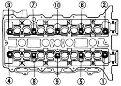
| Fig. 15:Cylinder head bolt (loosening sequence; tighten
in reverse order) -- 626 and MX6 2.0L (FS) engines
|
-
Clean all gasket mating surfaces. Inspect the cylinder head for damage,
cracks, and water and oil leakage. Check the head gasket surface for distortion
using a straight-edge and feeler gauge. Maximum allowable distortion is
0.004 inch (0.10mm).
To install:
- Position a new cylinder head gasket on the cylinder
block, and install the cylinder head.
- Apply clean engine oil to the bolt threads and seating
faces. Install new cylinder head bolts and tighten in 2-3 steps, in sequence,
to 13-16 ft. lbs. (17-22 Nm).
- Paint a mark on the edge of each cylinder head bolt
to use as a reference. Turn each bolt, in sequence, 90 degrees. Again,
turn each bolt, in sequence, an additional 90 degrees.
- Apply clean engine oil to the hydraulic lifters and
install them in their original positions. Make sure they move freely in
the bores.
- Install the camshafts and sprockets. Install the
distributor and connect the distributor/coil connectors.
- Install the timing belt and cover.
-
Install a new cylinder head cover gasket on the cylinder head cover.
Apply sealant to the cylinder head surface in the area adjacent to the
front camshaft caps, then install the cover. Tighten the bolts in 5-6
steps, in sequence, to 61-95 inch lbs. (7-11 Nm).
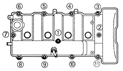
| Fig. 16:Cylinder head cover (bolt tightening sequence) --
626 and MX6 2.0L (FS) engines
|
- Connect the hoses to the cylinder head cover. Connect
the spark plug wires.
- Install the exhaust manifold and the alternator bracket.
Tighten the bracket nut and bolt to 19 ft. lbs. (25 Nm).
- Install the alternator belt and adjust the tension.
- Loosely install the power steering pump through and
lockbolts. Connect the pump pressure switch connector.
- Install the power steering pump belt and adjust the
tension. Tighten the pump through-bolt to 45 ft. lbs. (61 Nm) and the
lockbolt to 34 ft. lbs. (46 Nm).
- Install the power steering pump belt shield and tighten
the bolts to 86 inch lbs. (9 Nm). Install the power steering hose brackets
to the cylinder head cover, and tighten the bolts to 88 inch lbs. (10
Nm).
- Install the coolant temperature sensor housing with
a new gasket. Tighten the bolts to 19 ft. lbs. (25 Nm). Connect the electrical
connectors at the housing.
- Connect and adjust the accelerator cable.
- Connect the heater, brake vacuum, purge, fuel, water
and upper radiator hoses.
- Install the air cleaner assembly, fresh air duct
and splash shield.
- Connect the negative battery cable. Fill and bleed
the cooling system. Run the engine and check for proper operation.
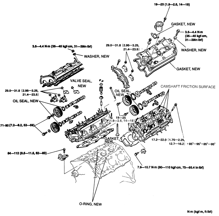
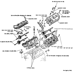
| Fig. 17: Exploded view of the cylinder head assembly --
929 with 3.0L (JE-ZE) engines
|
- Properly relieve the fuel system pressure.
- Disconnect the negative battery cable, and drain
the cooling system.
- Remove the air cleaner and air intake pipe.
- Remove the cooling fan and fan shroud.
- Disconnect and mark the spark plug wires and remove
the spark plugs. Remove the idler pulleys and the accessory drive belts.
- Remove the coolant bypass hose and the upper radiator
hose. Disconnect the electrical connector and remove the distributor.
- Hold the crankshaft pulley with a suitable tool and
remove the bolt. Remove the crankshaft pulley. Be careful not to damage
the sensor rotor.
- Remove the timing belt covers. Rotate the crankshaft
until the camshaft and crankshaft sprocket timing marks are aligned.
- Remove the upper idler pulley and the tensioner and
pulley. Mark the direction of rotation on the timing belt and remove the
timing belt.
- Disconnect the accelerator cable.
- Disconnect the harness connectors and remove the
mounting bolts from the dynamic chamber (upper intake manifold plenum).
- Disconnect and plug the fuel lines. Label and disconnect
the engine electrical connectors.
- Loosen the lower intake manifold bolts in 2-3 steps.
Remove the lower intake manifold.
- Remove the bolts from the transmission dipstick tube
bracket and the coolant bypass pipe.
- Disengage the heated oxygen sensor connector. Disconnect
the exhaust pipe from the exhaust manifolds. Remove the exhaust manifold
insulators and the manifolds.
- Remove the cylinder head covers.
- Hold the camshaft with a wrench on the hexagon cast
into the camshaft and remove the camshaft sprocket bolt. Remove the camshaft
sprockets.
- Remove the bolts from the front camshaft cap on the
left cylinder head. Loosen the remaining camshaft cap bolts in 2-3 steps
in the proper sequence. Mark the position of the caps so they can be reinstalled
in their original positions. Remove the caps and remove the camshafts.
Label the camshafts so they can be reinstalled in their proper locations.
- Remove the rocker arms.
- Loosen the cylinder head bolts in 2-3 steps, in the
reverse of the tightening sequence. Remove the bolts and remove the cylinder
heads.
- Clean all gasket mating surfaces. Inspect the cylinder
head for cracks or other damage. Check the cylinder head for warpage using
a feeler gauge and a straightedge. The maximum allowable distortion is
0.004 in. (0.10mm).
- Measure the length of the cylinder head bolts, from
just under the bolt head to the tip of the threads. The bolts should not
exceed 4.29 inches (109mm). Replace any bolts that exceed specification.
-
Clean the bolt threads and the threads in the cylinder block. Make
sure the bolts turn freely in the cylinder block.
To install:
- Install new cylinder head gaskets. On the left bank
the L mark on the gasket should face upward. On the right bank,
the R mark should face up.
-
Carefully install the cylinder heads. Lubricate the cylinder bolt threads
and head seat with clean engine oil and install the bolts. Tighten the
bolts as follows:
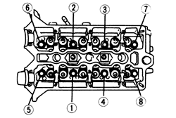
- Tighten the bolts, in sequence, to 12.7-16.2
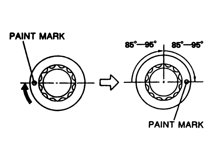
ft. lbs. (17-22 Nm).
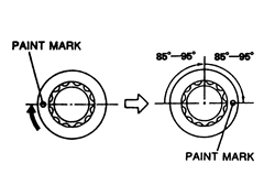
- Make a paint mark on each bolt head.
- Tighten each bolt, in sequence, 90 degrees.
-
Turn each bolt, in sequence, an additional 90 degrees.
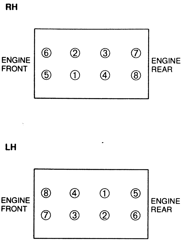
| Fig. 18: Cylinder head bolt tightening sequence
(loosen in reverse order) -- 1993-95 929 3.0L (JE-ZE) engines
|
| Fig. 19: Cylinder head bolt torque procedure --
1993-95 929 3.0L (JE-ZE) engines
|
- Lubricate the rocker arms with clean engine oil and
install them over the valve stems and hydraulic lash adjusters.
- Lubricate the camshaft lobes and journals with clean
engine oil and install the camshafts on the cylinder heads. Apply clean
engine oil to the lips of the new camshaft seals and install them on the
camshafts.
- Apply a small amount of silicone sealant to the cylinder
head on the front camshaft cap mating surfaces. Do not allow sealant to
get on the camshaft journal, oil seal face or camshaft thrust face.
- Install the camshaft caps in their original locations.
Gradually tighten the cap bolts, in sequence, to 24 ft. lbs. (32 Nm).
Tighten the front cap bolts on the left cylinder head to 95 inch lbs.
(11 Nm).
- Hold the camshafts using a wrench on the hexagon
cast into the camshaft. Install the camshaft sprockets with the retaining
bolts. Tighten the sprocket bolts on the right cylinder head to 59 ft.
lbs. (80 Nm) and the sprocket bolts on the left cylinder head to 19 ft.
lbs. (25 Nm).
- Apply sealant to the cylinder head in the areas adjacent
to the front camshaft caps. Install the cylinder head covers and tighten
the nuts to 39 inch lbs. (4 Nm).
- Using new gaskets, install the exhaust manifolds.
Tighten the nuts to 21 ft. lbs. (28 Nm). Install the exhaust manifold
insulators and tighten the bolts to 19 ft. lbs. (25 Nm).
- Connect the exhaust pipes to the exhaust manifolds
with new gaskets. Tighten the flange nuts to 38 ft. lbs. (52 Nm). Connect
the heated oxygen sensor.
- Install the bolts attaching the coolant bypass pipe
and the transmission dipstick tube.
- Install the lower intake manifold using new gaskets.
Tighten the mounting nuts, in 2-3 steps, to 19 ft. lbs. (25 Nm). Connect
the fuel lines.
- Connect the engine electrical connectors.
- Install the upper intake manifold plenum (dynamic
chamber) to the lower intake manifold, using a new gasket. Tighten the
bolts to 19 ft. lbs. (25 Nm), and engage the harness connectors.
- Connect the accelerator cable.
- Position the timing belt tensioner on a press. Place
a flat washer at the bottom of the tensioner body to prevent damage to
the body plug. Slowly press in the tensioner rod, but do not exceed 2200
lbs. Insert a pin in the tensioner body to hold the rod in place, then
install the tensioner and tighten the mounting bolts to 19 ft. lbs. (25
Nm).
- Make sure the crankshaft and camshaft sprocket timing
marks are properly aligned. Install the timing belt over the sprockets
and pulleys in the following order: crankshaft sprocket, lower idler pulley,
left cylinder head exhaust cam sprocket, left cylinder head intake cam
sprocket, tensioner pulley, right cylinder head exhaust cam sprocket and
right cylinder head intake cam sprocket.
- Push the belt down and install the upper idler pulley.
Tighten the upper idler pulley bolt to 38 ft. lbs. (52 Nm). Make sure
the camshaft and crankshaft sprocket timing marks are still aligned after
installing the upper idler pulley.
- Turn the crankshaft 2 revolutions in the normal direction
of rotation and realign the timing marks. Make sure all timing marks are
correctly aligned.
- Remove the pin from the automatic tensioner and again
rotate the crankshaft 2 turns. Confirm that the timing marks are aligned.
- Install the timing belt covers and tighten the bolts
to 95 inch lbs. (11 Nm).
- Install the crankshaft pulley. Hold the pulley with
a suitable tool and tighten the pulley bolt to 123 ft. lbs. (167 Nm).
Be careful not to damage the sensor rotor.
- Install the spark plugs and the distributor assembly.
Connect the spark plug wires and the distributor electrical connector.
- Install the upper radiator hose and water bypass
hose. Install the idler pulleys and accessory drive belts. Adjust the
belt tension.
- Install the shroud and cooling fan. Install the air
cleaner and ducts.
- Connect the negative battery cable. Fill and bleed
the cooling system. Change the engine oil.
- Start the engine and bring to normal operating temperature.
Check for leaks. Check the ignition timing and idle speed.
- Relieve the fuel system pressure. Disconnect the
negative battery cable.
- Drain the engine coolant.
- Raise and safely support the vehicle.
- Disconnect the oxygen sensor connectors. Remove the
exhaust pipe-to-manifold nuts and lower the exhaust pipes.
- Remove the right-hand three-way catalytic converter.
Lower the vehicle.
- Remove the Lysholm compressor (supercharger).
- Remove the intake manifold.
-
Remove the timing belt covers and timing belt.
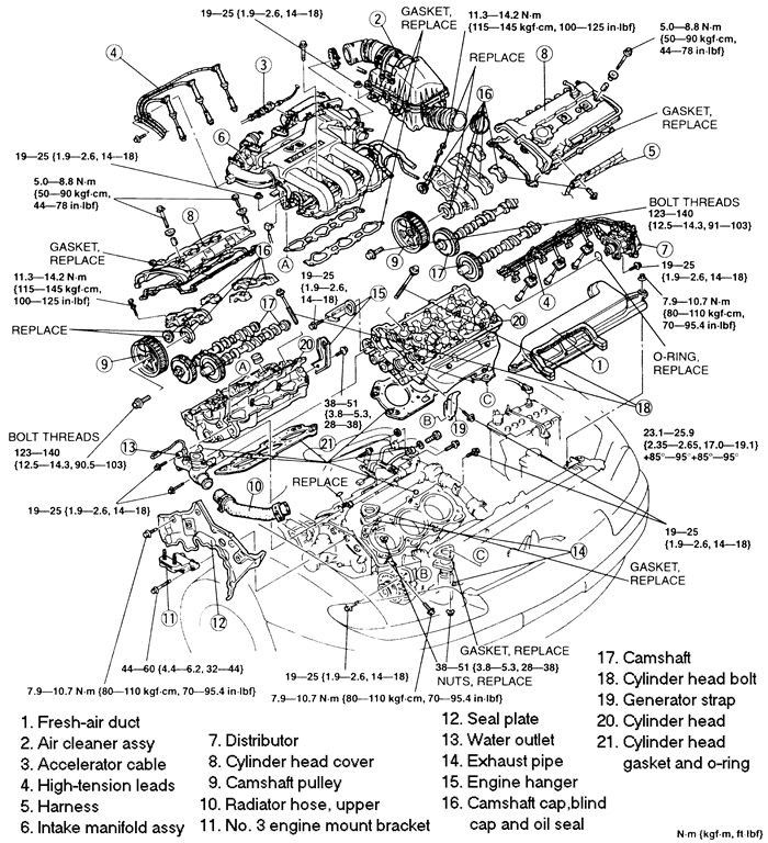
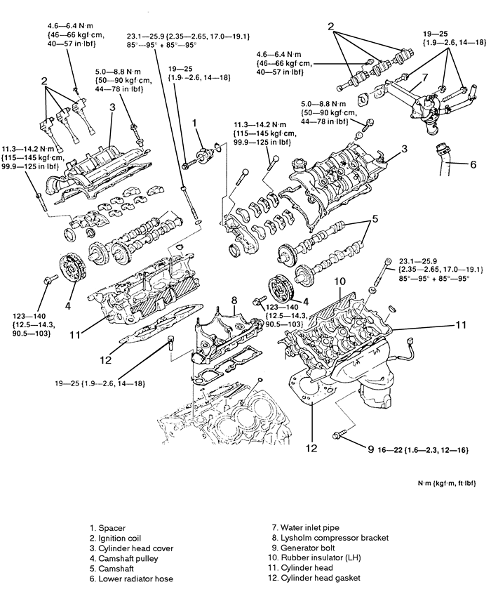
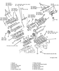
| Fig. 20: Cylinder head assembly (exploded view) --
1995-97 Millenia 2.3L (KJS) engines
|
- Remove the spacer and O-ring from the front of the
camshaft.
- Remove the ignition coils.
- Remove the cylinder head cover mounting bolts, in
5-6 steps, using the reverse of the tightening sequence. Remove the cylinder
head cover.
- Remove the camshaft sprockets.
- Turn the camshafts so the knock pins are aligned
with the marks on the camshaft caps. This will reduce the pressure on
the adjustment shims.
- Note the markings on the camshaft caps prior to removal,
so they can be reinstalled in the same positions. The right hand (rear)
caps are marked with numbers and the left hand (front) caps are marked
with letters.
- Loosen the front camshaft cap bolts in sequence,
in 5-6 steps. Remove the front camshaft caps.
- Remove the remaining camshaft cap bolts in the proper
sequence. Remove the caps, being sure to remove the thrust caps last.
Do not damage the cylinder head thrust bearing support.
- Remove the camshafts and oil seals.
- Remove the lifters and adjustment shims. Identify
and mark each lifter as it is removed so it can be reinstalled in the
same position.
- Remove the lower radiator hose and water inlet pipe.
- Remove the Lysholm compressor bracket.
- Remove the alternator bracket bolt to gain additional
clearance.
- Remove the rubber insulator from the left-hand cylinder
head.
- Temporarily install the number three engine mount,
which was removed with the timing belt, to support the engine. Remove
the engine support device.
- Loosen the cylinder head bolts, in 2-3 steps, in
the reverse order of the torque sequence. Remove the bolts and remove
the cylinder heads.
- Remove the oil control plug O-rings.
-
Clean all gasket mating surfaces. Inspect the cylinder head for damage,
cracks, and water and oil leakage. Check the head gasket surface for distortion
using a straight-edge and feeler gauge. Maximum allowable distortion is
0.004 inch (0.10mm).
To install:
- Apply clean engine oil to the O-rings, and install
them onto the oil control plugs.
- Position new head gaskets on the cylinder block.
The gaskets cannot be interchanged between sides and are marked R
and L for right and left side.
-
Install the cylinder heads. Apply clean engine oil to the threads of
new cylinder head bolts and install. Tighten the cylinder head bolts in
2-3 steps, in sequence, to 17-19 ft. lbs. (23-26 Nm).
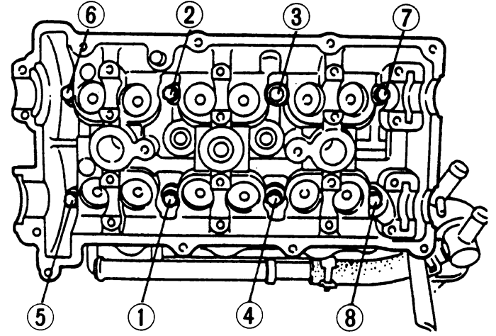
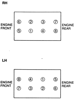
| Fig. 21: Cylinder head bolt (tightening sequence) --
1995-97 Millenia 2.3L (KJS) engines
|
- Paint a mark on the edge of each cylinder head bolt
to use as a reference. Turn each bolt, in sequence, 90 degrees. Again,
turn each bolt, in sequence, an additional 90 degrees.
- Install the rubber insulator onto the left-hand cylinder
head.
- Fit the knock sensor harness into the drill hole
on the cylinder block. Pass the harness under the rubber insulator.
- Install an engine support device, and remove the
number three engine mount.
- Install the alternator bracket bolt. Tighten the
mounting bolt to 12-16 ft. lbs. (16-22 Nm).
- Install the Lysholm compressor bracket. Tighten the
mounting bolts to 14-18 ft. lbs. (19-25 Nm).
- Install the water inlet pipe. Tighten the mounting
bolts to 14-18 ft. lbs. (19-25 Nm). Install the lower radiator hose.
- Apply clean engine oil to the lifters, then install
them in their original positions. Verify that they move smoothly in their
bore.
- Install new oil seals on the camshafts. Apply clean
engine oil to the camshaft lobes, journals and supports.
- Install the camshafts so the gear marks align.
- Remove all oil and dirt from the mating surfaces
between the front camshaft cap and the cylinder head.
- Install the thrust caps. Tighten the thrust cap bolts,
in 5-6 steps, until the caps are fully seated on the cylinder head.
- Apply silicone sealant, at a thickness of 0.06-0.09
inch (1.5-2.5mm), to the cylinder head surface in the area forward of
the camshaft gear cavity.
- Install the remaining camshaft caps in their original
positions. Tighten the caps, in sequence, in five equal steps, with the
final step being 100-125 inch lbs. (11-14 Nm).
- Apply clean engine oil to the lip of the new camshaft
oil seal. Push the seal in lightly by hand. Tap the seal in evenly with
a seal installer (49 F401 337A or equivalent) with a final protrusion
of 0-0.02 inch (0-0.5mm). Tap in a new blind cap.
- Install the camshaft sprockets. Tighten the mounting
bolts to 91-103 ft. lbs. (123-140 Nm).
- Measure and adjust valve clearances.
- Remove any sealant and gasket material from the cylinder
head cover contact surfaces.
- Apply silicone sealant to the cylinder head in the
area adjacent to the front and rear camshaft caps. Install a new gasket
on the cylinder head.
-
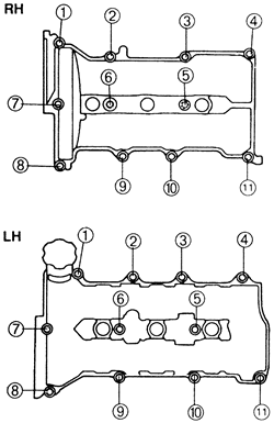
Install the cylinder head cover. Tighten the bolts in 5-6 steps, in
sequence, to 44-78 inch lbs. (5-9 Nm).
| Fig. 22: Cylinder head cover (tightening sequence) --
1995-97 Millenia 2.3L (KJS) engines
|
- Using a new O-ring, install the distributor.
- Install the ignition coils.
- Install the spacer, using a new O-ring. Tighten the
mounting bolt to 14-18 ft. lbs. (19-25 Nm).
- Install the timing belt and timing belt cover.
- Install the intake manifold.
- Install the Lysholm compressor (supercharger).
- Raise and safely support the vehicle.
- Install the right-hand three-way catalytic converter.
- Connect the exhaust pipes to the manifolds and tighten
the nuts to 28-38 ft. lbs. (38-51 Nm). Connect the oxygen sensor connectors.
Lower the vehicle.
- Connect the negative battery cable.
- Fill and bleed the coolant system.
- Run the engine and check for leaks.
- Relieve the fuel system pressure, and disconnect
the negative battery cable.
- Drain the cooling system.
- Remove the fresh air duct and the air cleaner assembly.
- Install an engine support device. Remove the timing
belt covers and timing belt.
- Remove the spark plug wires and distributor.
- Remove the intake manifold.
- Remove the upper radiator hose and water outlet.
- Temporarily install the number three engine mount
bracket, which was removed with the timing belt, to support the engine.
Remove the engine support device.
- Remove the seal plate from the front of the engine.
- Raise and safely support the vehicle.
- Disconnect the oxygen sensor connectors. Remove the
exhaust pipe-to-manifold nuts and lower the exhaust pipes. Lower the vehicle.
- Remove the alternator bracket.
- Disconnect the ventilation pipe from the left cylinder
head cover, remove the bolts and remove the cylinder head covers.
- Remove the camshaft pulleys.
- Remove the camshafts.
- Remove the hydraulic lifters. Identify each lifter
as it is removed so it can be reinstalled in the same position. If the
lifters are to be reused, store them upside down in an oil-filled sealed
container.
- Loosen the cylinder head bolts, in 2-3 steps, in
the reverse order of the torque sequence. Remove the bolts and remove
the cylinder heads.
-
Clean all gasket mating surfaces. Inspect the cylinder head for damage,
cracks, and water and oil leakage. Check the head gasket surface for distortion
using a straight-edge and feeler gauge. Maximum allowable distortion is
0.004 in. (0.10mm).
To install:
- Position new head gaskets on the cylinder block.
The gaskets cannot be interchanged between sides and are marked R
and L for right and left side.
-
Install the cylinder heads. Apply clean engine oil to the threads of
new cylinder head bolts and install. Tighten the cylinder head bolts in
2-3 steps, in sequence, to 17-19 ft. lbs. (23-26 Nm).
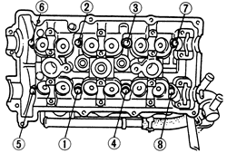
| Fig. 23: Cylinder head bolt (tightening sequence) --
1995-97 Millenia 2.5L (KLD) engine
|
- Paint a mark on the edge of each cylinder head bolt
to use as a reference. Turn each bolt, in sequence, 90 degrees. Again,
turn each bolt, in sequence, an additional 90 degrees.
- Apply clean engine oil to the hydraulic lifters and
install them in their original positions. Make sure they move freely in
the bores.
- Install the camshafts.
- Install the camshaft pulleys.
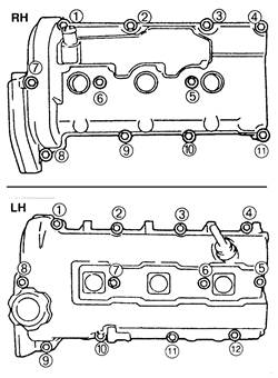
-
Apply sealant to the cylinder head surface in the area of the front
and rear camshaft caps. Install new gaskets and install the cylinder head
covers. Tighten the bolts in 5-6 steps, in sequence, to 44-78 inch lbs.
(5-9 Nm).
| Fig. 24: Cylinder head cover (tightening sequence) --
1995-97 Millenia 2.5L (VIN KLD) engine
|
- Install the alternator bracket. Tighten the mounting
bolts to 14-18 ft. lbs. (19-25 Nm).
- Raise and safely support the vehicle.
- Connect the exhaust pipes to the manifolds and tighten
the nuts to 28-38 ft. lbs. (38-51 Nm). Connect the oxygen sensor connectors.
Lower the vehicle.
- Install the seal plate, and tighten the mounting
bolts to 70-95 inch lbs. (8-11 Nm).
- Install an engine support device, and remove the
number three engine mount bracket.
- Install the water outlet. Tighten the mounting bolts
to 14-18 ft. lbs. (19-25 Nm). Install the upper radiator hose.
- Install the intake manifold using new gaskets. Tighten
the mounting bolts to 14-18 ft. lbs. (19-25 Nm).
-
Install the distributor:
- Apply clean engine oil to a new O-ring, and position
it on the distributor.
- Apply clean engine oil to the drive blade. Install
the distributor with the blade fit into the camshaft groove.
- Hand tighten the mounting bolts.
- Install the spark plug wires.
- Install the timing belt and timing belt covers.
- Install the air cleaner assembly and the fresh air
duct.
- Connect the negative battery cable.
- Fill and bleed the cooling system.
- Adjust the ignition timing and idle speed. Run the
engine and check for proper operation.
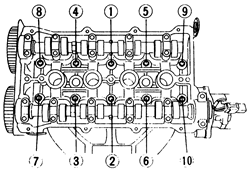
| Fig. 25: Cylinder head torque sequence -- 1993 Miata
1.6L (B6-ZE) engine
|
- Disconnect the negative battery cable and remove
the engine undercover.
- Remove the air ducts from the air cleaner and throttle
body.
- Tag and disconnect the spark plug wires from the
spark plugs. Remove the spark plugs and the distributor cap and wires
assembly. Remove the distributor.
- Drain the cooling system and disconnect the radiator
and heater hoses.
- Disconnect the exhaust pipe and remove the exhaust
manifold.
- On DOHC engines, remove the coolant bypass pipe.
- Disconnect the accelerator cable.
- Label and disconnect all necessary electrical connections
and vacuum hoses. Disconnect the fuel lines.
- Remove the intake manifold bracket and the intake
manifold.
- Remove the cylinder head cover bolts and the cylinder
head cover.
- Remove the timing belt cover(s). Rotate the crankshaft,
in the normal direction of rotation, until the No. 1 cylinder piston is
at TDC on the compression stroke. Make sure the timing marks on the crankshaft
and camshaft sprocket(s) are properly aligned and mark the direction of
rotation of the belt.
- Loosen the timing belt tensioner and remove the belt.
Do not rotate the crankshaft until the timing belt is reinstalled.
-
When everything is disconnected, loosen the cylinder head bolts in
the reverse of the tightening sequence. Remove the bolts and lift the
head off the engine.
To install:
- Thoroughly, clean the cylinder head and the block
contact surfaces. Examine the head gasket and check the cylinder head
for cracks. Check the cylinder head for warpage using a feeler gauge and
straightedge. The maximum allowable distortion is 0.006 in. (0.15mm) on
1.6L engine. The maximum allowable distortion is 0.004 in. (0.10mm) on
1.8L engine.
- Clean the cylinder head bolts and the threads in
the block. Make sure the bolts turn freely in the block.
- Install a new head gasket on the engine block. Make
sure the camshaft sprocket timing marks are still aligned, as set during
the removal procedure. Install the cylinder head.
- Lubricate the bolt threads and seat surfaces with
clean engine oil and install them. Torque the bolts in 2-3 steps to 56-60
ft. lbs. (75-81 Nm) in the proper sequence.
- Make sure the crankshaft and camshaft sprocket timing
marks are aligned, install the timing belt and set the tension. Carefully
rotate the crankshaft 2 turns to make sure the timing marks still line
up.
- Apply a thin bead of sealant to the cylinder head
cover and install the new gasket. Install the cover and torque the cover
bolts to 78 inch lbs. (9 Nm).
- Install the timing belt cover(s) and tighten the
bolts to 95 inch lbs. (11 Nm).
- Use new gaskets and install the manifolds. Torque
the intake manifold bolts/nuts to 19 ft. lbs. (25 Nm) and install the
intake manifold bracket. Torque the exhaust manifold nuts to 34 ft. lbs.
(46 Nm).
- Use a new gasket to connect the exhaust pipe and
torque the nuts to 34 ft. lbs. (46 Nm).
- If removed, install the radiator and connect all
cooling system hoses. On DOHC engines, install the coolant bypass pipe.
- Install the distributor, spark plugs, distributor
cap and wires.
- Connect all vacuum and fuel system hoses and connect
all wiring.
- Connect the accelerator cable and install the air
ducts and engine undercover.
- Connect the negative battery cable. Fill and bleed
the cooling system. Change the engine oil.
- Start the engine and bring to normal operating temperature.
Check for leaks. Check the ignition timing and idle speed.
- Relieve the fuel system pressure, and disconnect
the negative battery cable. Drain the cooling system.
- Remove the air cleaner assembly.
- Disconnect the accelerator cable.
- Tag and disconnect the spark plug wires from the
spark plugs. Remove the spark plugs.
- Disconnect the following hoses: heater, brake vacuum,
purge, fuel, water and cruise control.
- Label and disconnect the camshaft position sensor
and coil, heated oxygen sensor, steering pressure sensor, idle air control
valve, throttle position sensor, fuel injector and ground connectors.
- Remove the exhaust manifold heat shield.
- Remove the coolant bypass pipe.
- Remove the accessory drive belts. Remove the power
steering pump bolts and secure the pump aside with mechanics wire, leaving
the hoses attached.
- Remove the water pump pulley.
- Remove the alternator bracket nut and bolt, and position
the bracket aside.
- Disconnect the hoses from the cylinder head cover,
and loosen the cover bolts in 5-6 step sequences. Remove the cylinder
head cover.
- Remove the timing belt covers. Rotate the crankshaft,
in the normal direction of rotation, until the No. 1 cylinder piston is
at TDC on the compression stroke. Make sure the timing marks on the crankshaft
and camshaft sprocket(s) are properly aligned and mark the direction of
rotation of the belt.
- Loosen the timing belt tensioner and remove the belt.
Do not rotate the crankshaft until the timing belt is reinstalled.
- Remove the camshaft sprockets, and the camshaft.
- Remove the hydraulic lifters. Identify each lifter
as it is removed so it can be reinstalled in the same position. If the
lifters are to be reused, store them upside down in an oil-filled sealed
container.
- Disconnect the exhaust pipe and remove the exhaust
manifold.
-
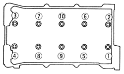
Loosen the cylinder head bolts, in 2-3 steps, in the correct sequence.
Remove the bolts and the cylinder head.
| Fig. 26: Cylinder head bolt (loosening sequence; tighten
in reverse order) -- 1995-97 Miata 1.8L (BPD) engines
|
To install:
- Thoroughly clean the cylinder head and the block
contact surfaces. Examine the head gasket and check the cylinder head
for cracks. Check the cylinder head for warpage using a feeler gauge and
straightedge. The maximum allowable distortion is 0.004 in. (0.10mm).
- Clean the cylinder head bolts and the threads in
the block. Make sure the bolts turn freely in the block.
- Install a new head gasket on the engine block. Make
sure the camshaft sprocket timing marks are still aligned, as set during
the removal procedure. Install the cylinder head.
- Lubricate the bolt threads and seat surfaces with
clean engine oil and install them. Torque the bolts in 2-3 steps to 56-60
ft. lbs. (75-81 Nm) in the proper sequence.
- Use new gaskets and install the manifold. Torque
the exhaust manifold nuts to 34 ft. lbs. (46 Nm).
- Use a new gasket to connect the exhaust pipe and
torque the nuts to 34 ft. lbs. (46 Nm).
- Apply clean engine oil to the hydraulic lifters and
install them in their original positions. Make sure they move freely in
the bores.
- Install the camshaft and sprockets.
- Make sure the crankshaft and camshaft sprocket timing
marks are aligned, install the timing belt and set the tension. Carefully
rotate the crankshaft 2 turns to make sure the timing marks still line
up.
- Apply a thin bead of sealant to the cylinder head
cover and install the new gasket. Install the cover and torque the cover
bolts to 44-78 in. lbs. (5-9 Nm).
- Install the timing belt cover(s) and tighten the
bolts to 95 inch lbs. (11 Nm).
- Install the alternator bracket. Tighten the bracket
nut and bolt to 19 ft. lbs. (25 Nm).
- Install the water pump pulley.
- Install the alternator belt and adjust the tension.
- Loosely install the power steering pump through and
lockbolts. Connect the pump pressure switch connector.
- Install the power steering pump belt and adjust the
tension. Tighten the pump through-bolt to 45 ft. lbs. (61 Nm) and the
lockbolt to 34 ft. lbs. (46 Nm).
- Install the power steering pump belt shield and tighten
the bolts to 86 inch lbs. (9 Nm). Install the power steering hose brackets
to the cylinder head cover, and tighten the bolts to 88 inch lbs. (10
Nm).
- Install the coolant bypass pipe.
- Install the exhaust manifold heat shield.
- Connect the electrical engine harness connectors.
- Connect the heater, brake vacuum, purge, fuel, water
and cruise control hoses.
- Install the spark plugs and wires.
- Connect and adjust the accelerator cable.
- Install the air cleaner assembly.
- Connect the negative battery cable. Fill and bleed
the cooling system. Change the engine oil.
- Check the ignition timing and properly adjust if
necessary.
- Start the engine and bring to normal operating temperature.
Check for leaks. Check the ignition timing and idle speed.