Previous Next

Power Rack and Pinion

REMOVAL AND INSTALLATION

1995-97 Protege
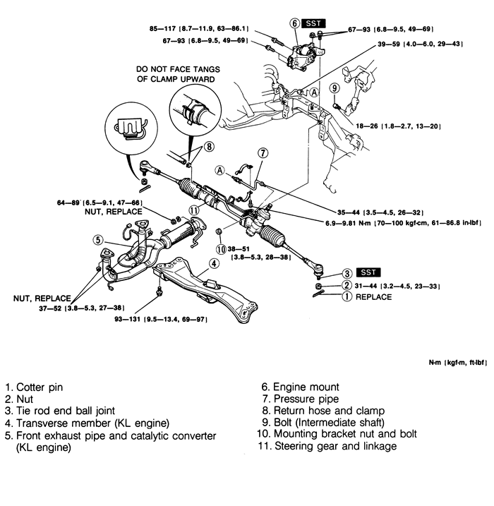
Fig. 1:Rack and pinion assembly and related components -- 626 and MX6

  1. Raise and safely support the vehicle. Remove the front wheels.
  2. Disconnect the tie-rod ends.
  3. Remove the splash shield, set plate and boot.
  4. Disconnect the return hose and pressure pipe.
  5. (M/T) Disconnect the extension bar/control rod.
  6. Safely support the engine and remove the rear engine mount bolt.
  7. Remove the rack mounting bracket nuts.
  8. Remove the rack through the right side of the vehicle.

    To install:

  9. Install the rack into the vehicle.
  10. Install the mounting bracket nuts. Torque the nuts in sequence to 28-38 ft. lbs. (38-51 Nm).
  11. Install the rear engine mount bolt.
  12. Connect the extension bar/control rod, if disconnected.
  13. Connect the return hose and pressure pipe.
  14. Install the splash shield, set plate and boot.
  15. Connect the tie-rod ends.
  16. Install the wheels and lower the vehicle.
  17. Adjust the front wheel alignment.
1993-95 929 and 1995 MX3
  1. Disconnect the negative battery cable. Raise and safely support the vehicle.
  2. Remove the front wheels.
  3. Remove the cotter pins and nuts, and separate the tie rod ends from the knuckles.
  4. Disconnect the power steering pressure and return lines.
  5. Mark the position of the steering shaft in the column universal joint. Remove the set plate and dust cover. Remove the universal joint pinch bolt.
  6. On manual transaxles (MTX) only, remove the control rod.
  7. Remove the mounting bolts and remove the steering gear.

    To install:

  8. Position the steering gear, making sure the marks made on the universal joint and steering gear shaft align, and install the mounting nuts and bolts. Tighten to 28-38 ft. lbs. (38-51 Nm). The bolts and nuts must be torqued in sequence.
  9. On MTX equipped vehicles, install the control rod. Tighten the mounting bolt to 12-16 ft. lbs. (16-22 Nm), and the mounting nut to 24-33 ft. lbs. (32-46 Nm).
  10. Install the universal joint pinch bolt, and tighten to 14-20 ft. lbs. (18-26 Nm).
  11. Connect the power steering lines.
  12. Connect the tie rod ends to the knuckles and tighten the nuts to 37-47 ft. lbs. (50-64 Nm). Install new cotter pins.
  13. Install the wheel and tire assemblies and lower the vehicle. Fill the power steering system with the proper type and quantity of fluid and bleed the air from the system.
  14. Check and adjust the front wheel alignment.
1993-97 626 and MX6
  1. Disconnect the negative battery cable. Raise and safely support the vehicle.
  2. Remove the front wheels.
  3. Remove the cotter pins and nuts, and separate the tie rod ends from the knuckles.
  4. If equipped with 2.5L engine, remove the transverse member and the front exhaust pipe.
  5. Support the engine with a suitable engine support tool (49 G017 502 or equivalent), and remove the rear engine mount.
  6. Disconnect the power steering pressure and return lines.
  7. Mark the position of the steering shaft in the column universal joint. Remove the universal joint pinch bolt.
  8. Remove the mounting bolts and remove the steering rack.

    To install:

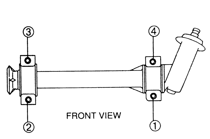
  9. Position the steering gear, making sure the marks made on the universal joint and steering gear shaft align, and install the mounting nuts and bolts. Tighten to 28-38 ft. lbs. (38-51 Nm). The bolts and nuts must be torqued in sequence.
    Fig. 2:Rack and pinion mounting bolt locations -- 1993-97 626 and MX6

  10. Install the universal joint pinch bolt and tighten to 13-20 ft. lbs. (18-26 Nm).
  11. Connect the power steering lines. Tighten the fluid fittings to the proper torque. Hand tighten the clamp bolts until snug, the torque them to 61-89 inch lbs. (7-10 Nm)
  12. Install the rear engine mount. Tighten the mounting bolts and nut to 50-68 ft. lbs. (67-93 Nm). Remove the engine support tool.
  13. If equipped with 2.5L engine, install the front exhaust pipe, using new gaskets. Tighten the pipe-to-catalytic converter nuts to 47-65 ft. lbs. (64-89 Nm) and the pipe-to-exhaust manifold nuts to 27-38 ft. lbs. (37-52 Nm). Connect the oxygen sensors.
  14. If equipped with 2.5L engine, install the transverse member and tighten the bolts to 69-96 ft. lbs. (94-131 Nm).
  15. Connect the tie rod ends to the knuckles.
  16. Install the wheel and tire assemblies and lower the vehicle. Fill the power steering system with the proper fluid and bleed the air from the system.
  17. Check the front wheel alignment.
1995-97 Millenia
  1. Raise and safely support the vehicle.
  2. Separate the tie-rod end from the steering knuckle.
  3. Remove the transverse member.
  4. Disconnect the return hose and pressure pipe.
  5. Remove the intermediate shaft bolt.
  6. Support the engine from the top and remove the engine mount member.
  7. Remove the bolts for engine mount No. 1.
  8. Remove the upper lateral link bolt and nut.
  9. Remove the lower arm bolt (crossmember side).
  10. Disconnect the stabilizer control link.
  11. Support the crossmember using a jack and remove the nuts and bolts.
  12. Lower the crossmember slowly and remove the stabilizer bar from the crossmember.
  13. Remove the mounting bracket bolts and remove the steering rack.

    To install:

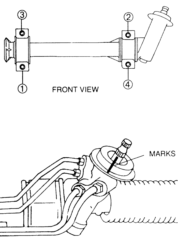
    Fig. 3:Mounting bracket and intermediate shaft alignment marks -- 1995-97 Millenia

  14. Replace the steering rack and loosely install the mounting bracket bolts. Looking straight ahead at the rack mounting bolts torque in the following order: lower left, upper right, upper left and lower right. Torque the bolts to 32-44 ft. lbs. (44-60 Nm).
  15. Install the stabilizer and torque the mounting bolts to 32-44 ft. lbs. (44-60 Nm).
  16. Install the crossmember.
  17. Connect the stabilizer control link, torque the nuts to 32-44 ft. lbs. (44-60 Nm).
  18. Install the lower arm bolt, torque to 58-86 ft. lbs. (79-116 Nm).
  19. Install the upper lateral link nut and bolt, torque to 58-86 ft. lbs. (79-116 Nm).
  20. Install the No. 1 engine mount bolts and torque to 32-44 ft. lbs. (44-60 Nm).
  21. Install the engine mount member, torque the bolts to 50-68 ft. lbs. (67-93 Nm) and the nuts to 55-77.3 ft. lbs. (75-104 Nm).
  22. Install the intermediate shaft bolt, torque to 14-19 ft. lbs. (18-26 Nm).
  23. Connect the pressure pipe and return hose.
  24. Install the transverse member.
  25. Connect the tie-rod end, torque the nut to 41-59 ft. lbs. (55-80 Nm).
  26. Lower the vehicle. Check the power steering fluid and fill to proper level.
1995-97 Miata
  1. Disconnect the negative battery cable. Raise and safely support the vehicle, and remove the wheel and tire assemblies.
  2. Remove the engine undercover.
  3. Remove the cotter pins and nuts, and disconnect the tie rod ends.
  4. Remove the steering column universal joint bolt. Matchmark the joint to the pinion shaft.
  5. Disconnect the hydraulic lines, and drain the fluid into a container.
  6. Remove the bracket bolts, and remove the steering rack from the vehicle.

    To install:

  7. When fitting the rack into place, make sure the pinion shaft and universal joint matchmarks are correctly aligned. Fit the shaft into the joint and start the steering rack bracket nuts or bolts.
  8. Tighten the bracket bolts to 34-43 ft. lbs. (47-58 Nm). Install the universal joint bolt and torque it to 14-19 ft. lbs. (18-26 Nm).
  9. Connect the tie rod ends, and torque the nuts to 22-33 ft. lbs. (30-44 Nm). Install a new cotter pin.
  10. Connect the power steering hydraulic lines and install the undercover.
  11. Install the wheel and tire assemblies, and lower the vehicle. If equipped with power steering, fill the system with the proper fluid and bleed the air from the system.
  12. Adjust the front alignment.
1993-95 RX7
  1. Raise and safely support the vehicle. Remove the wheel and tire assemblies. Remove the undercover.
  2. Remove the cotter pins and nuts from the tie rod ends. Separate the tie rod ends from the knuckles using a suitable tool.
  3. Remove the stabilizer bar brackets.
  4. Disconnect the power steering pressure and return lines.
  5. Mark the position of the steering gear shaft in the lower column joint and remove the bolt.
  6. Remove the steering gear bracket mounting bolts.
  7. Support the crossmember with a jack and remove the nuts and bolts. Slowly lower the crossmember and remove the steering gear.

    To install:

  8. Position the steering gear on the crossmember and raise the crossmember into position. Tighten the crossmember mounting nuts and bolts.
  9. Install the steering gear mounting bracket bolts and tighten, in sequence, to 28-38 ft. lbs. (38-51 Nm).
  10. Connect the column joint to the steering shaft, aligning the marks made during removal. Install the bolt and tighten to 14-19 ft. lbs. (18-26 Nm).
  11. Connect the power steering lines. When connecting the pressure hose, align the pin on the hose with the hole in the steering gear.
  12. Install the stabilizer bar brackets and tighten the bolts to 14-19 ft. lbs. (18-26 Nm).
  13. Connect the tie rod ends to the knuckles.
  14. Install the wheel and tire assemblies and lower the vehicle. Fill the power steering system with the proper type and quantity of fluid and bleed the air from the system.
 
Previous Next