Previous Next

Strut Assembly

REMOVAL & INSTALLATION

1990–94 Vehicles

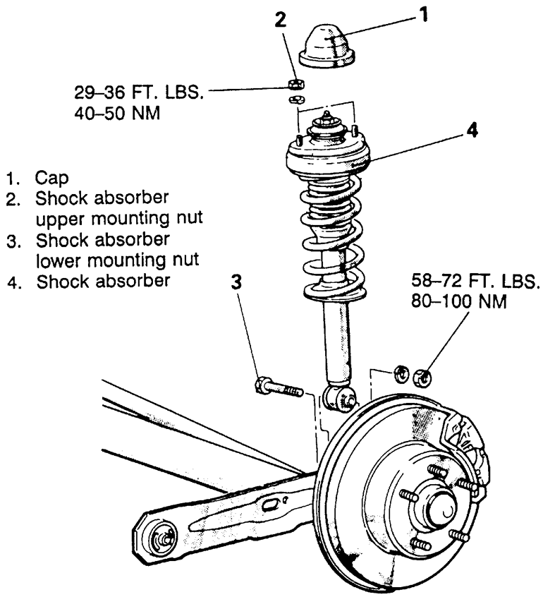
Fig. 1: Exploded view of the rear shock and strut assembly — 1990–94 FWD vehicles

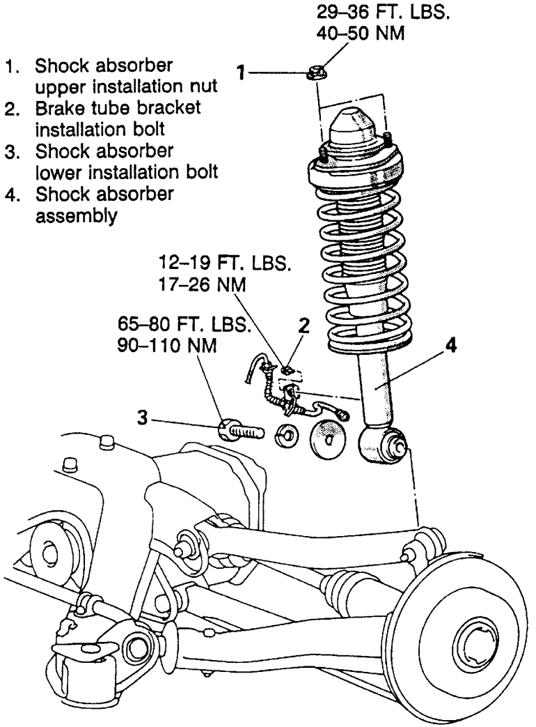
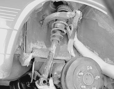
Fig. 2: Rear strut and shock assembly and related components — 1990–94 AWD vehicles

  1. Disconnect the negative battery cable. Remove the trunk interior trim to gain access to the top mounting nuts.
  2. Remove the top cap and upper shock mounting nuts.
  3. Remove the brake tube bracket bolt.
  4. mc>Raise and safely support torsion axle and arm assembly slightly. Make sure the jack does not contact the lateral rod.

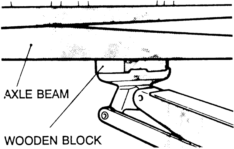
    NOTE: Always use a wooden block between the jack receptacle and the axle beam. Place the jack at the center of the axle beam.

    Fig. 3: Support axle beam with wooden block between jack and center of axle beam

  5. Remove the shock lower mounting bolt and remove the assembly from the vehicle.
  6. Installation is the reverse of the removal procedure. Tighten the upper shock mounting nuts to 29 ft. lbs. (40 Nm) and the lower mounting bolt to 72 ft. lbs. (100 Nm).
1995–98 Vehicles
  1. For all vehicles, except the Eclipse Spyder, remove the service lid in the luggage compartment. Open the luggage compartment, then unfasten the service lid retaining screws . . .

    . . . then remove the cover for access to the upper mounting nuts

  2. For the Eclipse Spyder, remove the luggage compartment side trim.
  3. Remove the cap and flange nuts securing the upper mounting bracket to the body of the vehicle. Do not remove the larger nut in the center of the shock absorber.

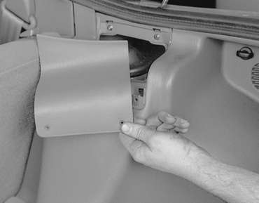
    Fig. 4: Remove the cap, exposing the upper mounting nuts

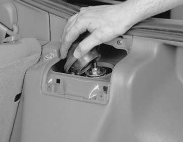
    Fig. 5: Unfasten the three outer retaining nuts. Do NOT remove larger center nut

  4. Raise and safely support the vehicle.
  5. Remove the bolt attaching the lower end of the shock to the knuckle and remove the shock absorber from the vehicle.

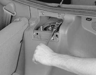
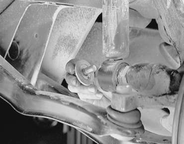
    Fig. 6: Once the vehicle is raised, loosen the lower shock-to-knuckle attaching bolt

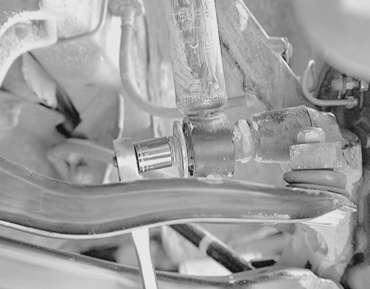
    Fig. 7: Remove the lower mounting bolt and washer . . .

    Fig. 8: . . . then carefully remove the shock and spring assembly from the vehicle

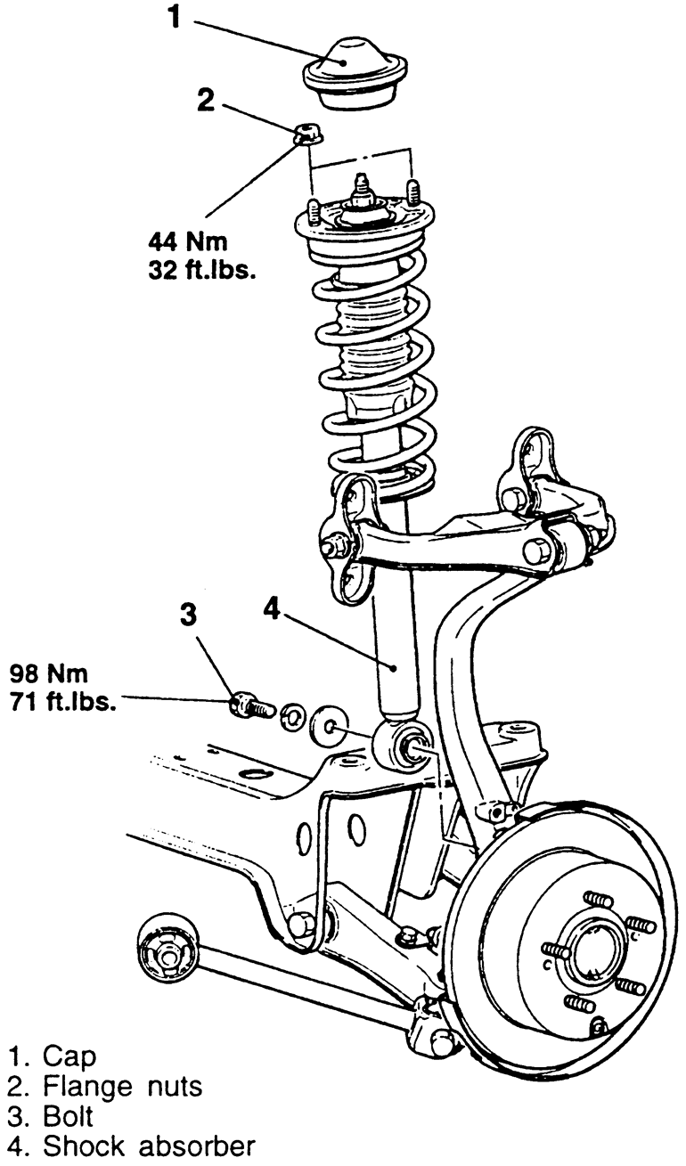
    Fig. 9: Exploded view of the shock and strut mounting — 1995–98 vehicles

    To install:

  6. Install the upper bracket of the shock to the vehicle. Tighten the mounting nuts to 32 ft. lbs. (44 Nm).
  7. Raise the suspension up with a jack or adjustable stand to align the shock absorber lower mounting holes.
  8. Install the lower mounting bolt. Tighten the bolt to 71 ft. lbs.
  9. Remove the jack or stand and safely lower the vehicle to the floor.
  10. Install the cap and service lid.

Previous Next