Previous Next

Brake Caliper

REMOVAL & INSTALLATION

  1. Disconnect the negative battery cable.
  2. Remove some of the brake fluid from the master cylinder reservoir. The reservoir should be no more than 12 full. When the pistons are depressed into the calipers, excess fluid will flow up into the reservoir.
  3. Raise the vehicle and support safely.
  4. Remove the appropriate tire and wheel assembly. For rear disc brakes, loosen the parking brake cable adjustment from inside the vehicle.
  5. If replacement or overhaul of the caliper is necessary, disconnect the brake hose from the caliper as follows:
    1. Hold the nut on the brake hose side and loosen the flared brake line nut.
    2. Remove the brake hose from the caliper.
  6. Remove the caliper guide and lock pins. Lift the caliper and slide the assembly toward the inside of the wheel well until it separates from the lock pin.

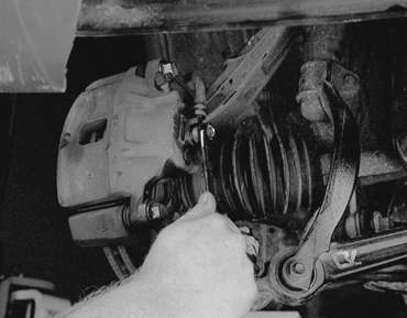
    Fig. 1: If replacing or overhauling the caliper, loosen the flared brake line bolt . . .

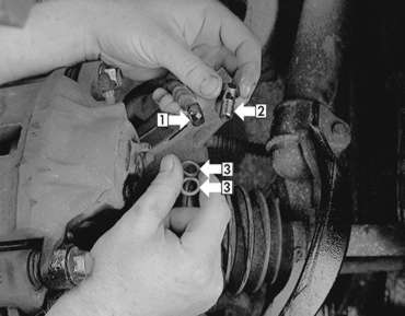
    Fig. 2: . . . then remove the brake hose (1), fitting (2) and gaskets (3)

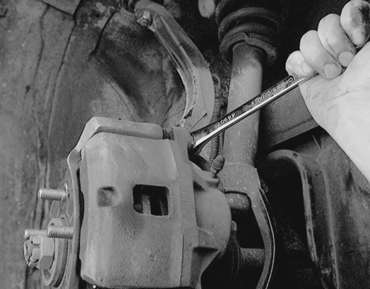
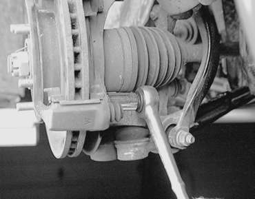
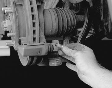
    Fig. 3: Unfasten the caliper guide pin . . .

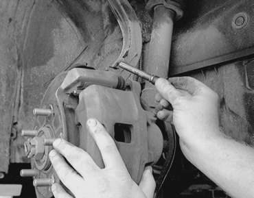
    Fig. 4: . . . then withdraw the pin from the caliper bore

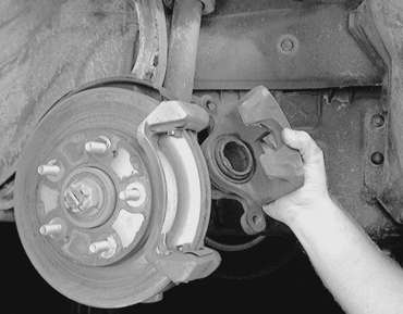
    Fig. 5: Lift the caliper away from the support

  7. If replacing the brake pads, suspend the caliper from the body with a suitable piece of wire. It is not necessary to disconnect the brake hose.

    Fig. 6: If you're just replacing the pads, you can suspend the caliper from the strut with a piece wire

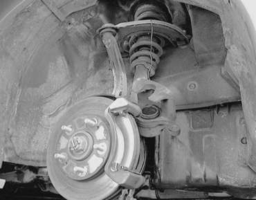
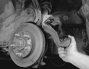
    Fig. 7: To remove the caliper support, unfasten the retaining bolts

    Fig. 8: Unfasten the support mounting bolts . . .

    Fig. 9: . . . then remove the support from the rotor

    To install:

  8. Position the caliper on the caliper support. Install the guide pin and lock pin. On some vehicles, there are markings to distinguish the guide and locking pins. Identification marks may also appear on the bolt heads. They should be installed in their original locations.

    Fig. 10: If equipped, install the guide and lock pins so the identification mark on the caliper body and head mark on the pins are aligned

  9. For front disc brakes, tighten the caliper retainers as follows:
    1. For 1990–94 vehicles, tighten the guide and locking pins to 23 ft. lbs. (32 Nm) on vehicles built up to May, 1989, and on vehicles built during and after May, 1989, tighten caliper guide and locking pins to 58–72 ft. lbs. (80–100 Nm).
    2. On 1995–98 vehicles, tighten the guide and locking pins to 65 ft. lbs. (88 Nm).
  10. For rear disc brakes, tighten the caliper retainers to 36–43 ft. lbs. (50–60 Nm).
  11. Install the brake hose onto the caliper with new washers in place. If equipped with brake hose retainer bolt, tighten bolt to 25 ft. lbs. (35 Nm) torque. If no bolt is used, tighten the brake hose fitting to 9–12 ft. lbs. (13–17 Nm) for 1990–94 vehicles. For 1995–98 vehicles, tighten the brake hose fitting to 11 ft. lbs. (15 Nm).

    NOTE: Do not twist the brake hose during installation.

  12. Install the wheel and tire assembly. Carefully lower the vehicle and connect the negative battery cable.
  13. If the brake line was disconnected, properly bleed the brake system.

Previous Next