Previous Next

Master Cylinder

REMOVAL & INSTALLATION

1990–94 Vehicles
  1. Disconnect the negative battery cable.
  2. Remove the master cylinder reservoir cap, then use a clean turkey baster or equivalent to siphon out as much fluid as possible and place in a suitable container. Install the cap.
  3. If equipped, detach the fluid level sensor connector.
  4. Disconnect the brake lines from the master cylinder. A separate fluid reservoir is used. Plug the lines to prevent drainage.
  5. Unfasten the 2 nuts securing the master cylinder to the brake booster, then remove the master cylinder.

    Fig. 1: Exploded view of the master cylinder-to-power booster mounting

    To install:

  6. Install master cylinder to the mounting studs and install the retaining nuts. Tighten the mounting nuts to 9 ft. lbs. (12 Nm).
  7. Unplug and install the brake lines to the master cylinder.
  8. Fill the reservoir to the proper level with clean DOT 3 brake fluid. Bleed the master cylinder.
  9. If equipped, attach the fluid level sensor.
  10. Apply the brake pedal and check for firmness. If the pedal is spongy,. air is present in the system. If air remains in the system, bleeding the entire system is required.
  11. Adjust the brake pedal, as outlined later in this section.
  12. Check the brakes for proper operation and leaks.
1995–98 Vehicles
  1. Disconnect the negative battery cable.
  2. Remove the master cylinder reservoir cap, then use a clean turkey baster or equivalent to siphon out as much fluid as possible and place in a suitable container. Install the cap.
  3. Disconnect and plug the lines from the brake master cylinder reservoir.

    Fig. 2: Unfasten the master cylinder reservoir mounting bracket bolts

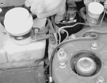
    Fig. 3: Unfasten the brake hose retaining clamps and disconnect the hose from the master cylinder

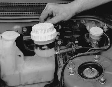
    Fig. 4: Detach the fluid level sensor connector, then remove the master cylinder reservoir

  4. Detach the fluid level sensor connector, unfasten the retainers, then remove the master cylinder reservoir.
  5. For vehicles equipped with manual transaxle, remove the clutch master cylinder reservoir bracket.
  6. For 2.0L non-turbo engines, perform the following:
    1. Disconnect the positive battery cable, then remove the battery.
    2. Remove the relay mounting bolts.
    3. Remove the washer tank mounting bolts and move the tank aside.

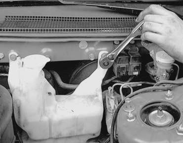
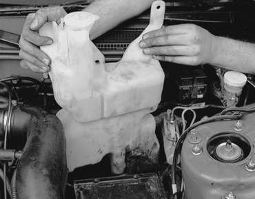
      Fig. 5: Unfasten the washer fluid reservoir tank mounting bolts. . .

      Fig. 6: . . . then remove the tank and position it out of the way

  7. For 2.0L turbo and 2.4L engines, perform the following:
    1. Remove the centermember mounting bolts.
    2. Remove the engine mount bracket.
    3. Unfasten the A/C compressor mounting bolts and position the compressor aside, but do NOT disconnect the refrigerant lines.
    4. Remove the A/C high pressure hose clamp, but do NOT disconnect the line.
    5. Disconnect the power steering pressure hose, pipe and return pipe clamp mounting bolts. Do NOT disconnect the fluid lines.
  8. Disconnect and plug the brake lines from the master cylinder.

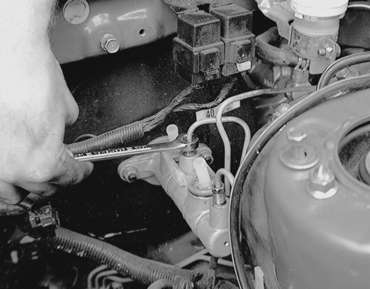
    Fig. 7: Use a flare nut wrench to disconnect and plug the brake lines from the master cylinder

  9. Unfasten the master cylinder-to-power booster retaining nuts, then remove the master cylinder from the vehicle.

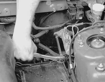
    Fig. 8: Unfasten the master cylinder-to-power booster retaining nuts . . .

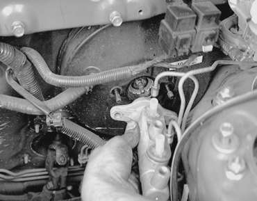
    Fig. 9: . . . then remove the master cylinder assembly from the vehicle

    Fig. 10: Exploded view of the master cylinder and power brake booster — 1995–98 vehicles

    To install:

  10. Adjust the clearance (A) between the brake booster pushrod and the primary piston as follows:

    Fig. 11: The brake booster pushrod and primary piston clearance (A) must be adjusted

    1. Calculate the clearance A from the B, C and D measurements, as shown in the accompanying figure. A equals B minus C minus D.
    2. The clearance should be 0.256–0.335 in. (0.65–0.858mm). When brake booster negative pressure 9.7 psi (67 kPa) is applied, then clearance value will become 0.004–0.012 in. (0.1–0.3mm).

      Fig. 12: Measuring the clearance of the pushrod-to-primary piston

  11. Install the master cylinder to the brake booster, then install the retaining nuts. Tighten the nuts to 7 ft. lbs. (10 Nm).
  12. Install the master cylinder reservoir, securing the retainers.
  13. Attach the fluid level sensor connector, then unplug and connect the fluid lines to the reservoir.
  14. The remainder of installation is the reverse of the removal procedure. Fill the reservoir with the proper type and amount of DOT 3 brake fluid from a fresh, sealed container.
  15. Bleed the brake system, as outlined later in this section.
  16. Adjust the brake pedal, as outlined later in this section.

Previous Next