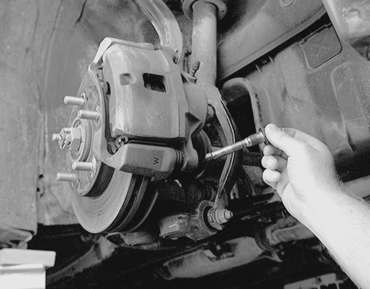
| Fig. 1: Location of the front caliper guide pin (bottom)
and lock pin (top)
|
| Fig. 3: Withdraw the caliper guide pin from the assembly
|
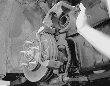
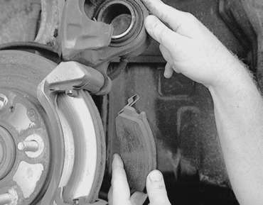
| Fig. 4: View of the brake pad assemblies with the
caliper lifted from the support
|
| Fig. 5: With the caliper lifted up away from the
support and remove the outer pad . . .
|
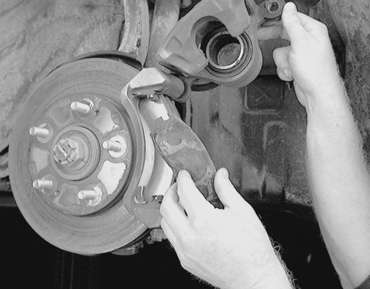
| Fig. 6: . . . then remove the inner pad from the
assembly
|
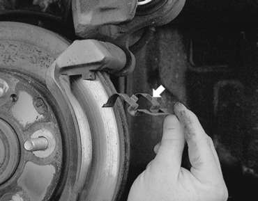
| Fig. 7: Remove the upper clip (see arrow) and inspect
it for damage . . .
|
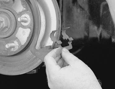
| Fig. 8: . . . there is also a bottom clip which should
be removed, inspected and replaced if necessary
|
| Fig. 9: Exploded view of the front disc brake pads
and related components — 1990–94 vehicles
|
| Fig. 10: Removing rear disc brake pads, shims and
spring clips from the caliper assembly
|
| Fig. 11: Use a spring scale to measure the hub turning
torque — front shown, rear similar
|
| Fig. 12: On front disc brakes you can use a suitable
clamp to press the piston into the caliper
|
| Fig. 13: For rear disc brakes, a driver tool to install
the piston into the caliper
|
| Fig. 14: Use the driver tool to thread the piston
into the rear caliper bore
|
To install:
NOTE: Be careful that the piston boot does not become caught when lowering the caliper onto the support. Do not twist the brake hose during caliper installation.
| Fig. 15: Measuring brake drag force
|