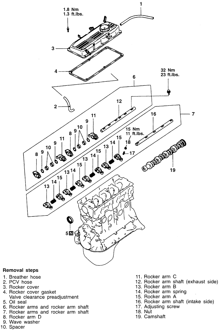
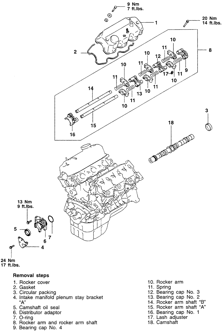
| Fig. 1: Camshaft, rocker arm and shaft assemblies — 1.5L
engine
|
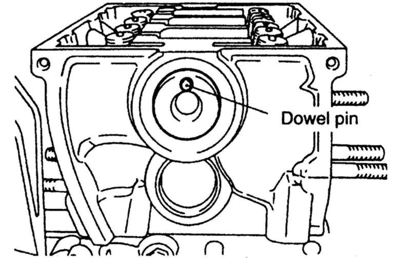
| Fig. 2: Positioning of the camshaft dowel pin — Mirage
1.5L (4G15) engine
|
NOTE: DO NOT allow the camshaft or the crankshaft to rotate after the timing belt is removed.
To install:
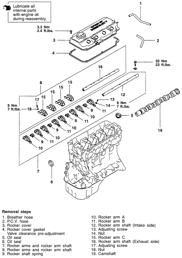
| Fig. 3: Camshaft, rocker arm and shaft assemblies — 1.8L
engine
|
WARNING
DO NOT allow the camshaft or the crankshaft to rotate after the timing belt
is removed!
To install:
| Fig. 4: Camshaft, rocker arm and shaft assemblies — 2.0L
SOHC engine
|
To install:
| Fig. 5: Camshaft and rocker arms — 1.6L
and 2.0L DOHC engines
|
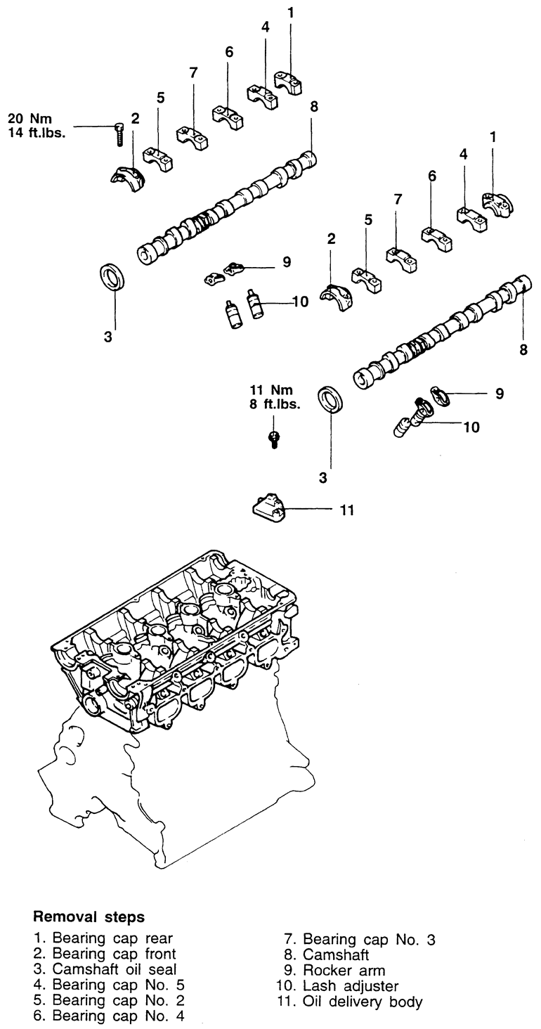
| Fig. 6: Camshaft bearing cap tightening sequence — 1.6L
and 2.0L DOHC engines
|
To install:
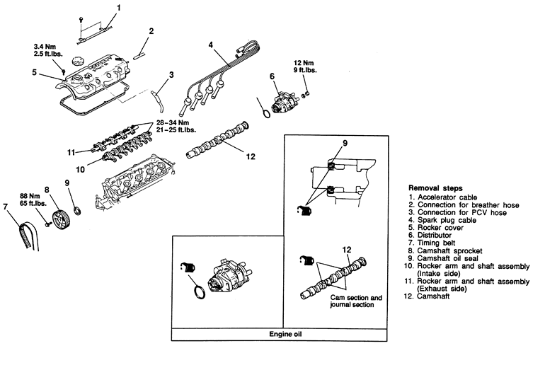
| Fig. 7: Camshaft, rocker arm and shaft assemblies — 2.4L
engine
|
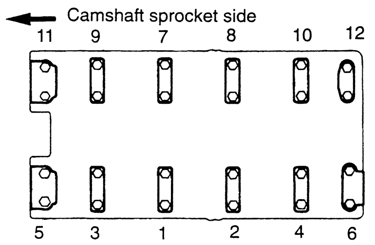
| Fig. 8: Camshaft identification — 2.4L
engine
|
NOTE: Always rotate the crankshaft in a clockwise direction. Make a mark on the back of the timing belt indicating the direction of rotation so it may be reassembled in the same direction if it is to be reused.
NOTE: If the bearing caps are difficult to remove, use a plastic hammer to gently tap the rear part of the camshaft.
NOTE: It is essential that all parts be kept in the same order and orientation for reinstallation. In order to prevent confusion during installation, be sure to mark and separate all parts.
To install:
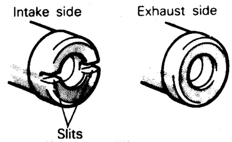
NOTE: Do not confuse the intake camshaft with the exhaust camshaft. The intake camshaft has a split on the rear face for driving the crank angle sensor.
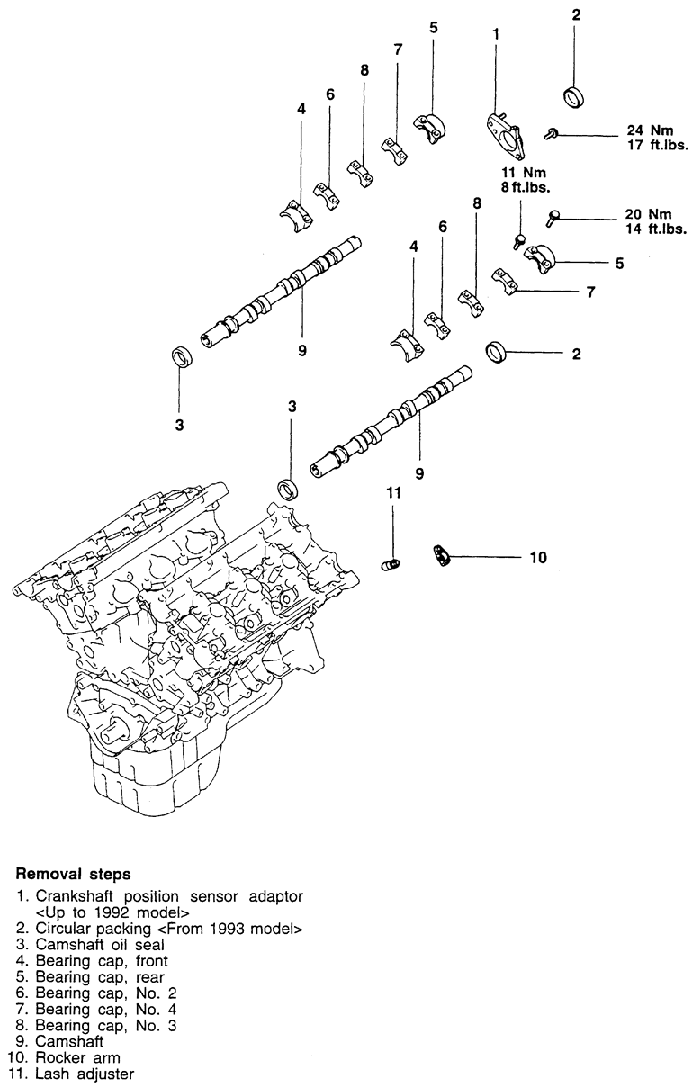
| Fig. 9: Camshaft, rocker arm and shaft assemblies — 3.0L
DOHC engine
|
| Fig. 10: Proper positioning of the camshaft knock pins — 3.0L
DOHC engine
|
WARNING
DO NOT rotate the crankshaft or camshafts after the timing belt has been
removed. If rotated, severe internal engine damage will result from the
pistons hitting the valves.
NOTE: Be sure to note the positioning of the knock pin at the end of the camshafts for reinstallation purposes.
NOTE: Be sure to keep the valve train components labeled and in proper order for reassembly.
NOTE: If the bearing caps are difficult to remove, use a plastic hammer to gently tap the components.
To install:
NOTE: Lubricate the valve train components with clean engine oil.
WARNING
Be sure to properly position the knock pins of the camshaft to prevent valve
to piston interference.
NOTE: Do not confuse the intake camshaft with the exhaust camshaft. The intake camshaft on the Diamante has a B or J stamped on the hexagon depending on the application. The exhaust camshaft on the Diamante has a D or K stamped on the hexagon depending on application.
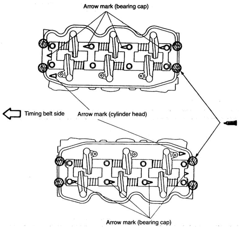
NOTE: Install the bearing caps according to the identification mark and cap number. Bearing caps No. 2, 3 and are marked as such. The caps also are marked I for intake or E for exhaust.
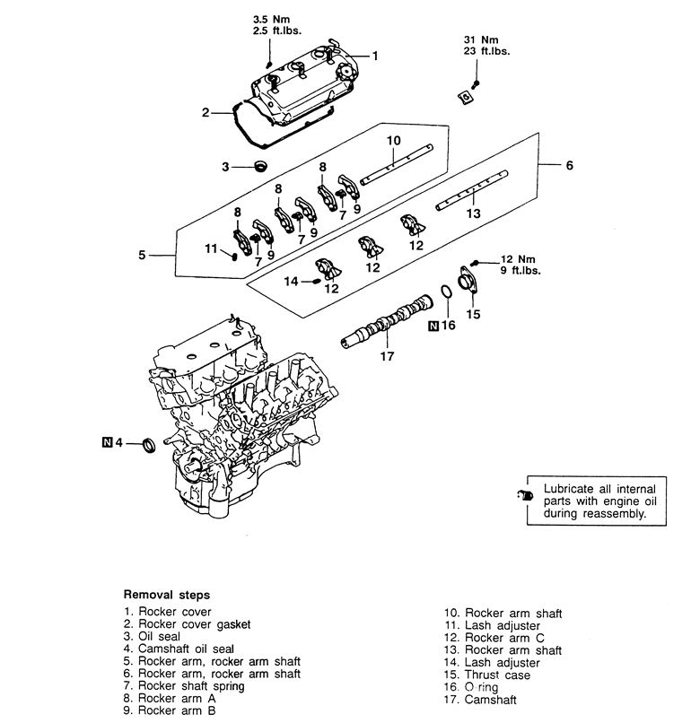
| Fig. 11: Camshaft, rocker arm and shaft assemblies — 3.0L
SOHC engine
|
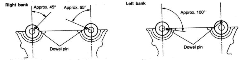
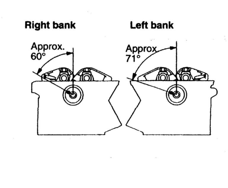
| Fig. 12: Right bank camshaft identification — 3.0L
SOHC engine
|
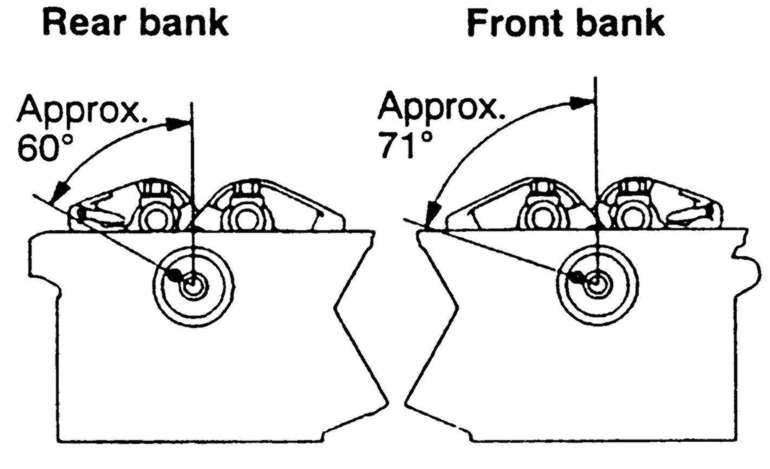
| Fig. 13: Proper positioning of the camshafts — 3.0L
SOHC engine
|
| Fig. 14: Alignment of the rocker shafts and application
of sealant — 3.0L SOHC engine
|
NOTE: Be sure to note the position of the rocker arms, rocker shafts and bearing caps for reinstallation purposes.
To install:
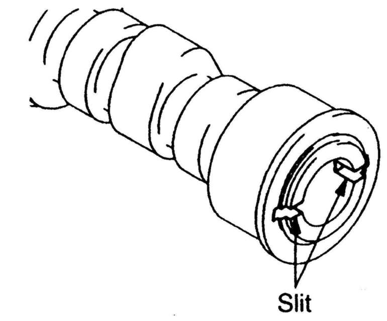
NOTE: The right bank camshaft is identified by a 4mm slit at the rear end of the camshaft.
To install:
| Fig. 15: Exploded view of the camshaft mounting — 3.5L
engine
|
| Fig. 16: Camshaft dowel position during installation — 3.5L
engine
|