Previous Next

TESTING

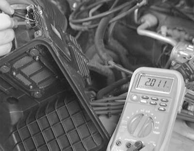
Fig. 2: Testing the resistance of the IAT sensor across the two sensor pins

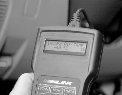
Fig. 3: The IAT sensor can be monitored with an appropriate and Data-stream capable scan tool

Fig. 4: IAT sensor terminal identification — 1990–93 Galant

Fig. 5: IAT sensor terminal identification — 2.4L engines

Fig. 6: Measure the intake air temperature sensor resistance while heating it with a hair drier

  1. Detach the air flow sensor electrical connector.
  2. Measure the resistance between terminals No. 4 and No. 6 of the electrical connector, except on the 2.0L DOHC turbo engine.
  3. If equipped with the 2.0L DOHC turbo engine, measure the resistance between terminals No. 6 and No. 8 of the sensor electric connector.
  4. Compare test readings to the following specifications:
    1. Sensor temperature of 32°F (0°C) — 5.3–6.7 kilo-ohms
    2. Sensor temperature of 68°F (20°C) — 2.3–3.0 kilo-ohms
    3. Sensor temperature of 176°F (80°C) — 0.30–0.42 kilo-ohms
  5. Measure the sensor resistance while heating the sensor area with a hair dryer. As the temperature of the sensor increases, sensor resistance should become smaller.
  6. If the measured resistance deviates from the standard value or the resistance remains unchanged, replace the air flow sensor assembly.

Previous Next