Previous Next

Fuel Rail and Injector(s)

REMOVAL & INSTALLATION

1.5L, 1.8L, And 2.0L SOHC Engines

Fig. 1: Exploded view of the fuel injectors and related components — 1.5L engine

Fig. 2: Exploded view of the fuel injectors and related components — 1.8L engine

Fig. 3: Exploded view of the fuel injectors and related components — 2.0L SOHC engine

  1. Relieve the fuel system pressure as described in this section.
  2. Disconnect the PCV hose from the valve cover. Also disconnect the breather hose at the opposite end of the valve cover.
  3. Remove the bolts holding the high pressure fuel line to the fuel rail and disconnect the line. Be prepared to contain fuel spillage; plug the line to keep out dirt and debris.

    CAUTION
    Observe all applicable safety precautions when working around fuel. Whenever servicing the fuel system, always work in a well ventilated area. Do not allow fuel spray or vapors to come in contact with a spark or open flame. Keep a dry chemical fire extinguisher near the work area. Always keep fuel in a container specifically designed for fuel storage; also, always properly seal fuel containers to avoid the possibility of fire or explosion.

  4. Remove the vacuum hose from the fuel pressure regulator.
  5. Disconnect the fuel return hose from the pressure regulator.
  6. Label and detach the electrical connectors from each injector.
  7. Remove the bolt(s) holding the fuel rail to the manifold. Carefully lift the rail up and remove it with the injectors attached. Take great care not to drop an injector. Place the rail and injectors in a safe location on the workbench; protect the tips of the injectors from dirt and/or impact.
  8. Remove and discard the injector insulators from the intake manifold. The insulators are not reusable.
  9. Remove the injectors from the fuel rail by pulling gently in a straight outward motion. Make certain the grommet and O-ring come off with the injector.

    To install:

  10. Install a new insulator in each injector port in the manifold.
  11. Remove the old grommet and O-ring from each injector. Install a new grommet and O-ring; coat the O-ring lightly with clean, thin oil.
  12. If the fuel pressure regulator was removed, replace the O-ring with a new one and coat it lightly with clean, thin oil. Insert the regulator straight into the rail, then check that it can be rotated freely. If it does not rotate smoothly, remove it and inspect the O-ring for deformation or jamming. When properly installed, align the mounting holes and tighten the retaining bolts to 7 ft. lbs. (9 Nm). This procedure must be followed even if the fuel rail was not removed.
  13. Install the injector into the fuel rail, constantly turning the injector left and right during installation. When fully installed, the injector should still turn freely in the rail. If it does not, remove the injector and inspect the O-ring for deformation or damage.
  14. Install the delivery pipe and injectors to the engine. Make certain that each injector fits correctly into its port and that the rubber insulators for the fuel rail mounts are in position.
  15. Install the fuel rail retaining bolts and tighten them to 9 ft. lbs. (12 Nm).
  16. Connect the wiring harnesses to the appropriate injector.
  17. Connect the fuel return hose to the pressure regulator, then connect the vacuum hose.
  18. Replace the O-ring on the high pressure fuel line, coat the O-ring lightly with clean, thin oil and install the line to the fuel rail. Tighten the mounting bolts.
  19. Attach the PCV hose and the breather hose if they were disconnected.
  20. Connect the negative battery cable. Pressurize the fuel system and inspect all connections for leaks.
1.6L and 2.0L DOHC Engines

Fig. 4: Exploded view of the fuel injectors and related components — 1.6L and 2.0L DOHC engines

  1. Relieve the fuel system pressure as described in this section.
  2. Disconnect the negative battery cable.
  3. Wrap the connection with a shop towel and disconnect the high pressure fuel line at the fuel rail.

    CAUTION
    Observe all applicable safety precautions when working around fuel. Whenever servicing the fuel system, always work in a well ventilated area. Do not allow fuel spray or vapors to come in contact with a spark or open flame. Keep a dry chemical fire extinguisher near the work area. Always keep fuel in a container specifically designed for fuel storage; also, always properly seal fuel containers to avoid the possibility of fire or explosion.

  4. Disconnect the fuel return hose and remove the O-ring.
  5. Disconnect the vacuum hose from the fuel pressure regulator.
  6. Disconnect the PCV hose. On 2.0L engine, remove the center cover.
  7. Label and detach the electrical connectors from each injector.
  8. Remove the injector rail retaining bolts. Make sure the rubber mounting bushings do not get lost.
  9. Lift the rail assembly up and away from the engine.
  10. Remove the injectors from the rail by pulling gently. Discard the lower insulator. Check the resistance through the injector. The specification for 2.0L turbocharged engine is 2–3 ohms at 70°F (20°C). The specification for the others is 13–15 ohms at 70°F (20°C).

    To install:

  11. Install a new grommet and O-ring to the injector. Coat the O-ring with light oil.
  12. Install the injector to the fuel rail.
  13. Replace the seats in the intake manifold. Install the fuel rail and injectors to the manifold. Make sure the rubber bushings are in place before tightening the mounting bolts.
  14. Tighten the retaining bolts to 72 inch lbs. (11 Nm).
  15. Attach the connectors to the injectors and install the center cover. Connect the PCV hose.
  16. Connect the fuel pressure regulator vacuum hose.
  17. Connect the fuel return hose.
  18. Replace the O-ring, lightly lubricate it and connect the high pressure fuel line.
  19. Connect the negative battery cable and check the entire system for proper operation and leaks.
2.4L Engine

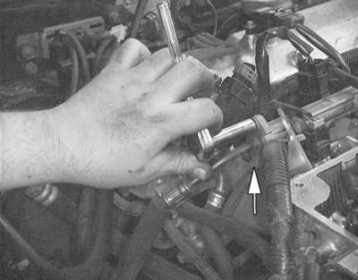
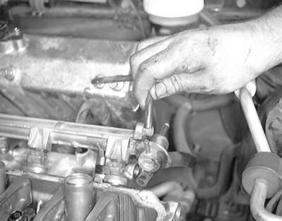
Fig. 5: Remove the fuel feed line-to-fuel rail retaining fitting bolts . . .

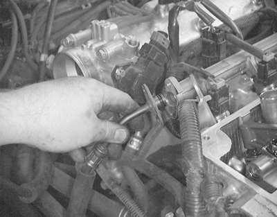
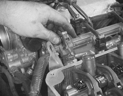
Fig. 6: . . . then remove the fuel feed line from the fuel injector rail

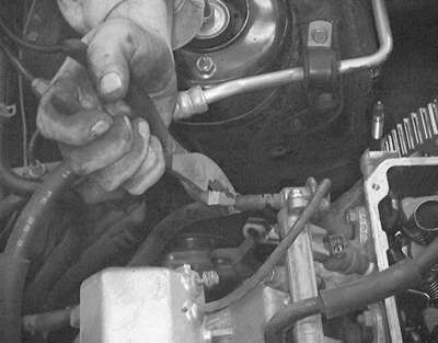
Fig. 7: Remove the hose clamp on the fuel return line . . .

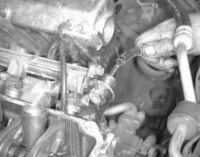
Fig. 8: . . . then disconnect the hose from the pressure regulator

Fig. 9: Remove the vacuum hose from the pressure regulator

Fig. 10: Detach the connectors from all of the fuel injectors

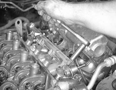
Fig. 11: Remove the two fuel rail retaining bolts . . .

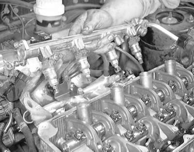
Fig. 12: . . . then lift the rail and the injectors from the intake manifold

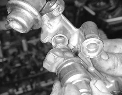
Fig. 13: Remove the fuel injectors from the rail by gently rocking them loose

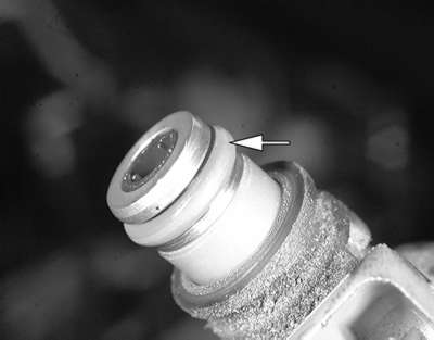
Fig. 14: Always replace the O-rings on the injectors before reinstalling them

  1. Relieve the fuel system pressure as described in this section.
  2. Label and disconnect the spark plug wires. Position the wires aside.
  3. Disconnect the PCV hose from the valve cover.
  4. Remove the bolts holding the high pressure fuel line to the fuel rail, then disconnect the line. Be prepared to contain fuel spillage; plug the line to keep out dirt and debris.

    CAUTION
    Observe all applicable safety precautions when working around fuel. Whenever servicing the fuel system, always work in a well ventilated area. Do not allow fuel spray or vapors to come in contact with a spark or open flame. Keep a dry chemical fire extinguisher near the work area. Always keep fuel in a container specifically designed for fuel storage; also, always properly seal fuel containers to avoid the possibility of fire or explosion.

  5. Remove the vacuum hose from the fuel pressure regulator.
  6. Disconnect the fuel return hose from the pressure regulator.
  7. Label and detach the electrical connectors from each injector.
  8. Remove the bolt(s) holding the fuel rail to the manifold. Carefully lift the rail up and remove it with the injectors attached. Take great care not to drop an injector. Place the rail and injectors in a safe location on the workbench; protect the tips of the injectors from dirt and/or impact.
  9. Remove and discard the injector insulators from the intake manifold. The insulators are not reusable.
  10. Remove the injectors from the fuel rail by pulling gently in a straight outward motion. Make certain the grommet and O-ring come off with the injector.

    To install:

  11. Install a new insulator in each injector port in the manifold.
  12. Remove the old grommet and O-ring from each injector. Install a new grommet and O-ring; coat the O-ring lightly with clean, thin oil.
  13. If the fuel pressure regulator was removed, replace the O-ring with a new one and coat it lightly with clean, thin oil. Insert the regulator straight into the rail, then check that it can be rotated freely. If it does not rotate smoothly, remove it and inspect the O-ring for deformation or jamming. When properly installed, align the mounting holes and tighten the retaining bolts to 7 ft. lbs. (9 Nm). This procedure must be followed even if the fuel rail was not removed.
  14. Install the injector into the fuel rail, constantly turning the injector left and right during installation. When fully installed, the injector should still turn freely in the rail. If it does not, remove the injector and inspect the O-ring for deformation or damage.
  15. Install the delivery pipe and injectors to the engine. Make certain that each injector fits correctly into its port and that the rubber insulators for the fuel rail mounts are in position.
  16. Install the fuel rail retaining bolts and tighten them to 9 ft. lbs. (12 Nm).
  17. Connect the wiring harnesses to the appropriate injector.
  18. Connect the fuel return hose to the pressure regulator, then connect the vacuum hose.
  19. Replace the O-ring on the high pressure fuel line, coat the O-ring lightly with clean, thin oil and install the line to the fuel rail. Tighten the mounting bolts to 4 ft. lbs. (6 Nm).
  20. Connect the PCV hose and spark plug wires.
  21. Connect the negative battery cable. Pressurize the fuel system and inspect all connections for leaks.
3.0L and 3.5L Engines

Fig. 15: Exploded view of the fuel injectors and related components — 3.0L engines

Fig. 16: Exploded view of the fuel injectors and related components — 3.5L engine

  1. Relieve the fuel system pressure.
  2. Disconnect the negative battery cable.

    CAUTION
    Work MUST NOT be started until at least 90 seconds after the ignition switch is turned to the LOCK position and the negative battery cable is disconnected from the battery. This will allow time for the air bag system backup power supply to deplete its stored energy, preventing accidental air bag deployment which could result in unnecessary air bag system repairs and/or personal injury.

  3. Drain the cooling system.
  4. Disconnect all components from the air intake plenum and remove the plenum from the intake manifold. Refer to Section 3.
  5. Wrap the connection with a shop towel and disconnect the high pressure fuel line at the fuel rail.

    CAUTION
    Observe all applicable safety precautions when working around fuel. Whenever servicing the fuel system, always work in a well ventilated area. Do not allow fuel spray or vapors to come in contact with a spark or open flame. Keep a dry chemical fire extinguisher near the work area. Always keep fuel in a container specifically designed for fuel storage; also, always properly seal fuel containers to avoid the possibility of fire or explosion.

  6. Disconnect the fuel return hose and remove the O-ring.
  7. Disconnect the vacuum hose from the fuel pressure regulator.
  8. Detach the electrical connectors from each injector.
  9. Remove the fuel pipe connecting the fuel rails. Remove the injector rail retaining bolts. Make sure the rubber mounting bushings do not get lost.
  10. Lift the rail assemblies up and away from the engine.
  11. Remove the injectors from the rail by pulling gently. Discard the lower insulator.

    To install:

    NOTE: Some of the vehicles may have a clip that secures the injector to the fuel rail. Be sure to remove or install the injector clip where necessary.

  12. Install a new grommet and O-ring to the injector. Coat the O-ring with light oil.
  13. Install the injector to the fuel rail.
  14. Replace the seats in the intake manifold. Install the fuel rails and injectors to the manifold. Make sure the rubber bushings are in place before tightening the mounting bolts.
  15. Tighten the retaining bolts to 7–9 ft. lbs. (10–13 Nm). Install the fuel pipe with new gasket.
  16. Attach the electrical connectors to the injectors.
  17. Connect the fuel return hose.
  18. Replace the O-ring, lightly lubricate it and connect the high pressure fuel line.
  19. Using new gaskets, install the intake plenum and all related items. Refer to Section 3.
  20. Fill the cooling system.
  21. Connect the negative battery cable and check the entire system for proper operation and leaks.

Previous Next