- Raise the vehicle and support safely.
- Remove the tire and wheel assembly.
- If equipped with rear disc brakes, remove the caliper from the disc and
remove the brake disc.
- Remove the dust cap and bearing nut. Do not use an air gun to remove the
nut.
- Remove the outer wheel bearing.
- Remove the drum and/or axle hub with the inner wheel bearing and the grease
seal.
- Remove the grease seal and remove the inner bearing.
To install:
- Lubricate the inner bearing and install to the drum or hub.
- Install a new grease seal.
- To determine if the self-locking nut is reusable:
- Screw in the self-locking nut until about 0.07–0.11 in. (2–3mm)
of thread is visible under the nut.
- Measure the torque required to turn the self-locking nut counterclockwise.
- The lowest allowable torque is 48 inch lbs. (6 Nm). If the measured
torque is less than the specification, replace the nut.
- Install the drum and/or hub to the vehicle.
- Lubricate and install the outer wheel bearing to the spindle.
- Tighten the self-locking nut to 108–145 ft. lbs. (150–200 Nm).
- Set up a dial indicator and measure the endplay while moving the hub or
drum in and out. If the endplay exceeds 0.008 in. (0.002mm), retorque the
nut. If still beyond the limit, replace the bearings.
- Install the grease cap and wheel assembly.
NOTE: Never disassemble the rear hub bearing. The wheel bearing
is serviced by replacement of the hub.
- If equipped with ABS, remove the wheel speed sensor.
- Raise and safely support the vehicle.
- Remove the rear wheel.
- Remove the caliper and brake disc or brake drum.
- Remove the dust cap and flange nut.
- Remove the rear hub assembly.
To install:
- Install the rear hub assembly using a new flange nut. Tighten the flange
nut to 130 ft. lbs. (180 Nm).
- Install the dust cap.
- Install the wheel speed sensor if removed. The air gap should be 0.012–0.035
in. (0.3–0.9mm).
- Install the brake disc and caliper, or brake drum.
- Install the rear wheel assembly and lower the vehicle to the floor.
- Raise the vehicle and support it safely.
- Remove the wheel and tire assemblies.
- Remove the grease cap and the hub nut.
- Remove the brake drum. The outer bearing will fall out while the drum is
coming off. Do not drop it. Remove the hub and rotor assembly.
- Pry out and discard the oil seal.
- Remove the inner bearing.
NOTE: Check the bearing races. If any scoring, heat checking
or damage is noted, they should be replaced. When bearing or races need
replacement, replace them as a set.
- If the bearings and races are to be replaced, drive out the race with a
brass drift.
To install:
- Before installing new races, coat them with wheel bearing grease. Drive
into place with proper size driver. Make sure they are fully seated.
- Thoroughly pack the bearings and lubricate the hubs with wheel bearing grease.
Install the inner bearing and coat the lip and rim of the grease seal with
grease. Drive the seal into place with a seal driver.
- Install the drum assembly on the axle.
- Lubricate and install the outer wheel bearing, washer and nut. To properly
adjust the wheel bearing preload:
- Tighten the wheel bearing nut to 20 ft. lbs. (27 Nm) while rotating
the drum.
- Back off the adjusting nut to remove the preload, then tighten it to
7 ft. lbs. (10 Nm).
- Install the nut lock and a new cotter pin.
- Install the wheel and lower the vehicle.
- Raise the vehicle and support safely.
- Remove the tire and wheel assembly.
- Remove the bolt(s) holding the speed sensor bracket to the knuckle and remove
the assembly from the vehicle.
WARNING
The speed sensor has a pole piece projecting from it. This exposed tip must
be protected from impact or scratches. Do not allow the pole piece to contact
the toothed wheel during removal or installation.
- Remove the caliper from the brake disc and suspend with a wire.
- Remove the brake rotor.
- Remove the grease cap, locking nut and tongued washer.
- Remove the rear hub and bearing assembly.
NOTE: The rear hub assembly can not be disassembled. If
bearing replacement is required, replace the assembly as a unit.
- If replacing the hub assembly, remove the two bolts securing the speed sensor
ring to the hub.
To install:
- Install the speed sensor to the hub and bearing assembly. Tighten the mounting
bolts to 8 ft. lbs. (11 Nm).
- Install the hub and bearing assembly to the axle shaft.
- Install the tongued washer and a new locking nut. Tighten the locknut to
144–188 ft. lbs. (200–260 Nm). Once the locknut has been properly
torqued, crimp the nut flange over the slot in the spindle, and install the
grease cap.
- Install the brake caliper and rotor.
- Install the speed sensor and tighten the mounting bolt to 8 ft. lbs. (11
Nm).
- Install the tire and wheel assembly.
WARNING
Be sure to pump the brake pedal until it's firm, before moving vehicle.
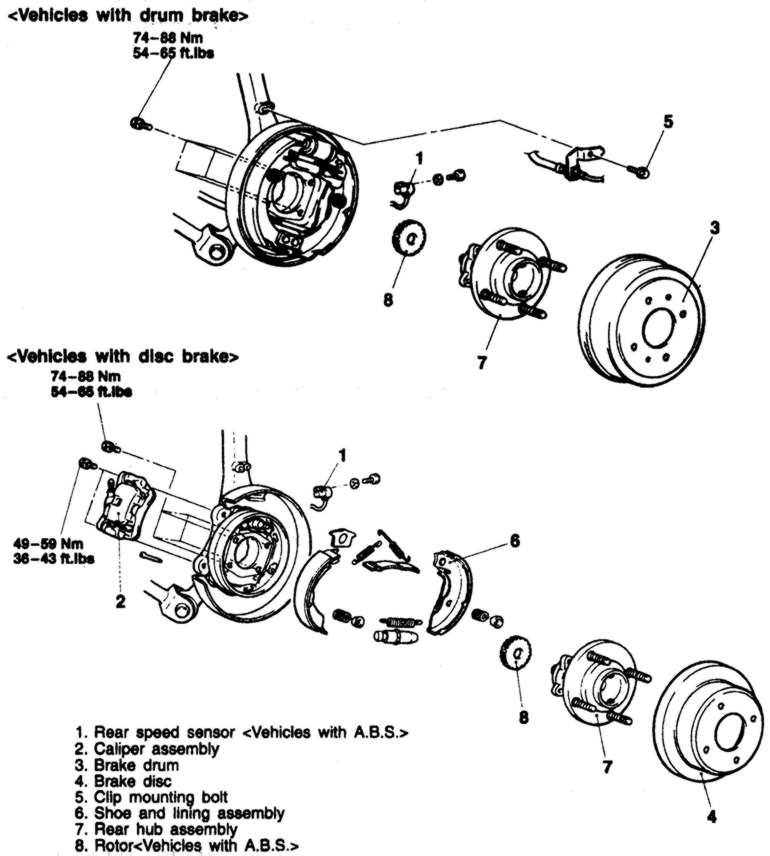
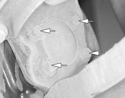
| Fig. 3: The hub and bearing assembly is retained to the
knuckle by four bolts
|
| Fig. 4: Use a press to remove the speed sensor rotor
from the hub — Galant
|
| Fig. 5: Exploded view of the rear hub/bearing assembly
and related components — Galant

|
To install
Press the wheel sensor rotor onto the hub.
Install the hub to the knuckle and tighten the mounting bolts to 54–65
ft. lbs. (74–88 Nm).
Install the brake drum on the hub.
If equipped with ABS, install the vehicle speed sensor.
Install the wheel assembly and lower the vehicle.
- Remove the cotter pin, halfshaft nut and washer.
- Raise the vehicle and support safely.
- Remove the appropriate wheel assembly.
- If equipped with ABS, remove the vehicle speed sensor.
- Remove the caliper and brake pads. Support the caliper out of the way
using wire.
- Remove the brake rotor from the hub assembly.
- Remove the parking brake shoes as follows:
- Remove the upper shoe to anchor springs.
- Remove the lower shoe to shoe spring.
- Remove the brake shoe hold-down springs.
- Disconnect the parking brake cable from the actuating lever.
- From the back of the knuckle, remove the four bolts securing the hub to
the knuckle.
- Remove the hub and bearing assembly from the knuckle.
NOTE: The hub assembly is not serviceable and should
not be disassembled.
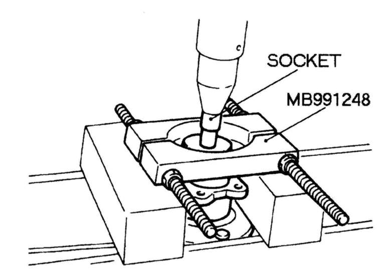
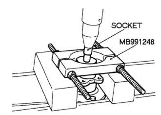
- If replacing the hub, use special socket MB991248 and a press to remove
the wheel sensor rotor from the hub.
To install
- Press the wheel sensor rotor onto the hub.
- Install the hub to the knuckle and tighten the mounting bolts to 54–65
ft. lbs. (74–88 Nm).
- Install the parking brake shoes.
- Position the rotor on the hub. Install a couple of lug nuts and lightly
tighten to hold rotor on hub.
- Install the caliper holder and place brake pads in holder. Slide caliper
over brake pads and install guide pins. Once caliper is secured, lug nuts
can be removed.
- If equipped with ABS, install the vehicle speed sensor.
- Install the wheel assembly and lower the vehicle.
NOTE: The hub assembly is not repairable; if defective, replacement
is the only option. If the hub is removed for any reason it must be replaced.
- Raise and support vehicle safely.
- Remove the both of the rear wheels.
- Remove the caliper and the brake disc. Support the caliper with wire to
prevent stress to the brake hose.
- If equipped with ABS, remove the bolt holding the speed sensor to the
trailing arm and remove the sensor.
NOTE: The speed sensor has a pole piece projecting from
it. This exposed tip must be protected from impact or scratches. Do not
allow the pole piece to contact the toothed wheel during removal or installation.
- Remove the grease cap, self-locking nut and tongued washer.
NOTE: Do not use an air gun to remove the hub locknut.
- Remove the rear hub assembly from the spindle.
- Remove the bolts that secure the ABS sensor ring to the hub and remove
the ring from the hub.
To install
- Secure the sensor ring to the hub assembly and tighten the mounting bolts.
- Install the hub assembly, tongued washer and a new self-locking nut. Tighten
the nut to 166 ft. lbs. (230 Nm), align with the indentation in the spindle,
and crimp.
- Using a rope around the hub bolts and a spring balance, measure the resistance
necessary to rotate the hub. If the resistance exceeds 7 ft. lbs. (13 Nm),
loosen and retighten the locknut. If the resistance still exceeds the specification,
the hub must be replaced.
- Using a dial indicator, measure the hub endplay. The endplay should be
0.002 inches (0.05mm) or less.
- Install the brake rotor and caliper assembly.
- Install the speed sensor to the knuckle.
NOTE: Route the speed sensor cable correctly. Improper
installation may cause cable damage and system failure. Use the white
stripe on the outer insulation to keep the sensor harness properly positioned.
- Use a brass or other non-magnetic feeler gauge to check the air gap between
the tip of the pole piece and the toothed wheel. Correct gap is 0.008–0.028
in. (0.2–0.7mm). Tighten the sensor bracket nut with the sensor located
so the gap is the same at several points on the toothed wheel. If the gap
is incorrect, it is likely that the toothed wheel is worn or improperly
installed.
- Bleed the brake system and install the rear wheels.