CAUTION
Brake pads and shoes contain asbestos, which has been determined to be a cancer
causing agent. Never clean the brake surfaces with compressed air! Avoid inhaling
any dust from brake surfaces! When cleaning brakes, use commercially available
brake cleaning fluids.
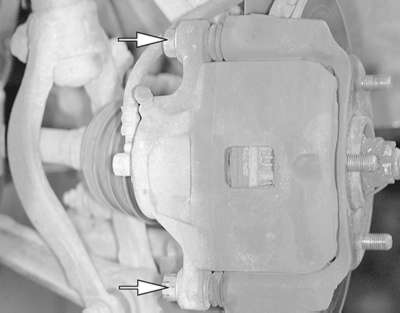
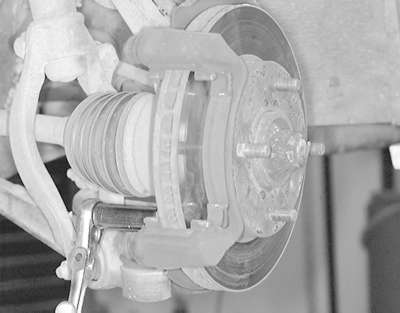
| Fig. 1: The brake caliper is mounted to the caliper
support with two bolts
|
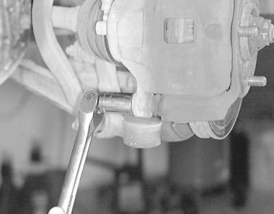
| Fig. 2: Remove the brake caliper-to- caliper support
retaining bolts
|
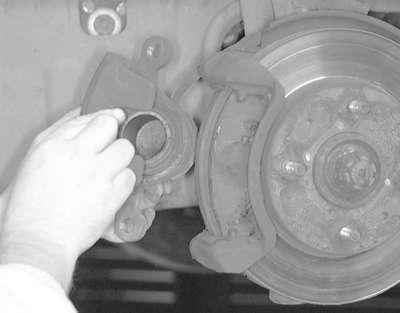
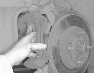
| Fig. 3: Grasp the caliper and lift it from the caliper
assembly from the caliper support . . .
|
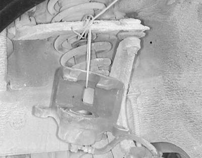
| Fig. 4: . . . then support it using mechanic's wire
or another suitable device
|
| Fig. 5: Remove the caliper bracket retaining bolts
. . .
|
| Fig. 6: . . . then remove the caliper bracket from
the vehicle
|
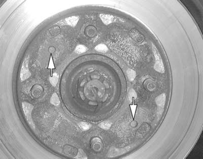
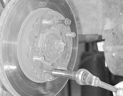
| Fig. 7: There are two threaded holes located on the
rotor
|
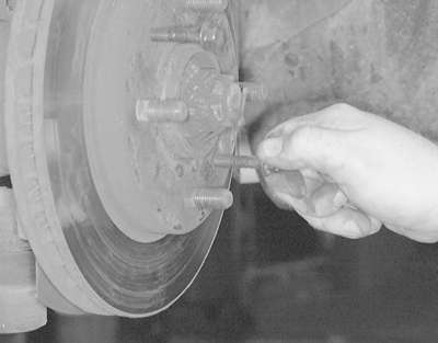
| Fig. 8: Install a suitable size bolt into the threaded
holes
|
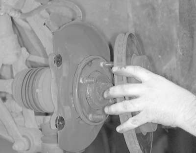
| Fig. 9: Tighten the bolts until they force the rotor
off of the hub . . .
|
| Fig. 10: . . . then remove the rotor from the hub assembly
|
The following procedure is applicable to both the front and rear brakes.
- Raise the vehicle and support safely.
- Remove the appropriate wheel.
- Remove the caliper and brake pads.
- Support the caliper out of the way using a wire.
- On some models the rotor is held to the hub by two small threaded screws.
Remove the screws and pull off the rotor.
To install
- Position the rotor on the hub and install the mounting screws.
- Install the caliper holder and brake pads.
- Slide the caliper over the brake pads and tighten the guide pins.
- Install the wheel and tighten the lug nuts.
WARNING
Pump the brake pedal several times before attempting to move vehicle.
- Loosen the large driveshaft nut while the vehicle is still on the ground
with the brakes applied.
- Raise and safely support vehicle.
- Remove appropriate wheel assembly.
- Remove the axle end nut and lock washer.
- Remove the caliper from its bracket.
WARNING
Do not allow the caliper to hang by the brake line.
- Remove the brake pads.
- Remove the ball joint and tie rod end from the lower control arm.
- Use and puller to push the halfshaft through the rotor/hub assembly.
- Remove the lower strut bolts and remove the assembly from the vehicle.
- To separate the rotor from the hub assembly, remove the rotor retainer
bolts and separate using tool MB991001 or equivalent.
To install:
- Assemble the rotor and hub. Tighten the nuts to 40 ft. lbs. (54 Nm) and
install the assembly to the vehicle.
- Install the washer so the chamfered edge faces outward. Install the nut
and tighten temporarily.
- Install the ball joint and tie rod end.
- Install the brake components.
- Install the wheel and lower the vehicle to the floor.
- Tighten the axle nut with the brakes applied to a maximum torque of 188
ft. lbs. (260 Nm). Install the cotter pin and bend to secure.
- Raise the vehicle and support safely.
- Remove appropriate wheel assembly.
- Detach the parking brake connection at the rear caliper assembly.
- Remove the caliper and brake pads.
- Support the caliper out of the way using wire.
- Remove the brake rotor from the rear hub assembly.
To install
- Position the rotor on the hub. Install a couple of lug nuts and lightly
tighten to hold rotor on hub.
- Install the caliper holder and place brake pads in holder.
- Slide caliper over brake pads and install guide pins. Once caliper is
secured, the lug nuts can be removed.
- Reconnect parking brake cable and install wheel(s).

