Previous Next

INSTALLATION

  1. Once the crankshaft has been cleaned, inspected or machined, the bearing clearance must be checked. this must be done in all cases, including reuse of old bearings or installation of thicker bearings. The bearing clearance (or oil clearance) is a critical dimension and must be proper before final assembly.
  2. Install the crankshaft into the block (the block is inverted) and make sure all bearing surfaces and journals are clean and dry. Cut pieces of plastic measuring media (such as Plastigage® or similar product) to fit the width of the bearing. Lay the piece widthwise across the journal. The insert must not rest on top of oil holes and the bearing shell that clamps against it must not be a grooved one.

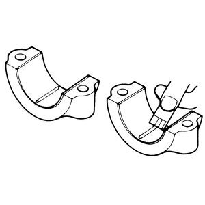
    Fig. 1: Use Plastigage® or a similar product to measure the oil clearance on the main bearings

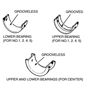
    Fig. 2: Locations of the various types of bearings — notches in the bearing caps correspond with tabs on the bearing

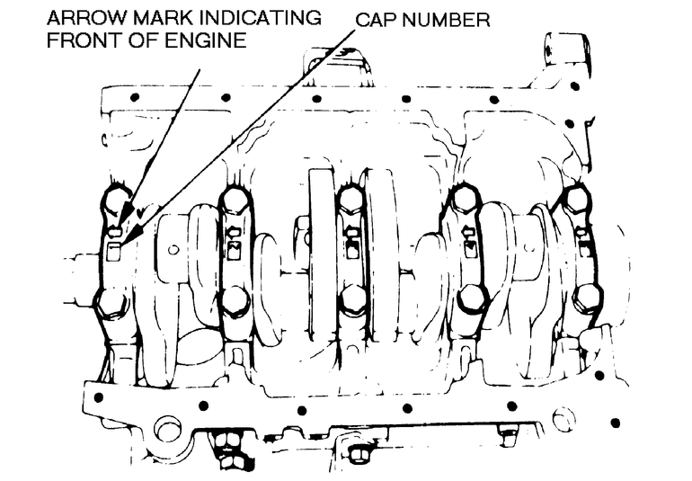
    Fig. 3: The bearing caps must be installed with the arrow facing the front of the engine and in proper order

  3. Install and tighten all rod and main bearing caps to specifications. Do NOT turn the crankshaft. Remove the caps and read the width of the measuring media at the widest point. This is done by comparing the width at its widest point to lines on the scale included with the package. If working on a V6 engine, install the bearing cap to the engine block as shown in the illustration. Tighten the bearing cap bolts to the specified torque in the sequence shown.
  4. If the bearing clearance is to specification, old bearings may be re-used if otherwise in good condition. In cases of moderate, regular wear, it may be feasible to replace the bearings with new ones of original size and avoid machining the crankshaft, provided this gives the specified clearance.
  5. If there is any question about the wear pattern or the ability of the new bearing shells to provide correct clearance, it is advisable to have the crankshaft machined and install matching bearings.
  6. Before final assembly, all bearing surfaces must be thoroughly lubricated with clean engine oil. Make sure the main bearings have the oil holes lined up and that the upper shells for bearings 1, 2, 4, and 5 have grooves so that oil will pass to the connecting rod journals.The center main bearings, both top and bottom, are groove-less but include thrust bearing surfaces (flanges). Make sure connecting rod bearings have the notches in the bearing and cap together. Make sure all main bearing caps are installed in their original positions and directions. Main bearing caps are numbered in order from front to rear and have an arrow indicating the front (crankshaft pulley) end of the engine. Bearing cap bolts should be tightened evenly in 3 stages to specification. Work in sequence, starting with the center main bearing cap, then moving to No. 2, No. 4, front, and rear caps.
  7. Reinstall the crankshaft seals, the oil pick–up screen and oil pan as soon as possible. Even if other work is to performed on the engine, the seals and pan will serve to protect the crankshaft, rods and bearings from dirt and impact damage.

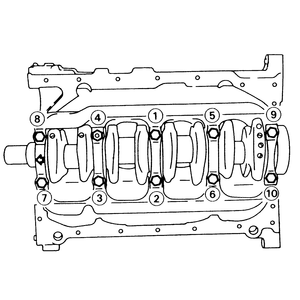
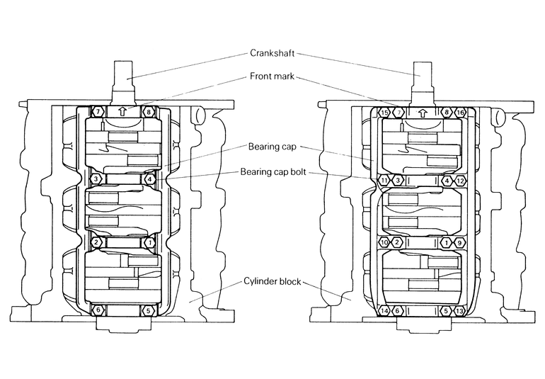
    Fig. 4: Tighten the bearing caps in the order shown to the specified torque — 4-cylinder Engines with one-piece or separate bearing caps

    Fig. 5: Tighten the bearing cap braces in the order shown and to the specified torque — 6-cylinder Engines

    Fig. 6: A common newer 4-cylinder engine crankshaft assembly with a one-piece bearing cap brace

Previous Next