NOTE: The 1993–95, rear-wheel drive 2.4L (California)
Pick-ups have the same engine controls as the 3.0L engines. All other 2.4L engines
are listed as 2.4L engines.
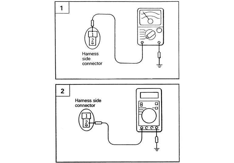
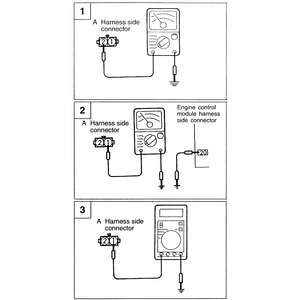
| Fig. 1: The ECT harness testing procedure — 2.4L
engines
|
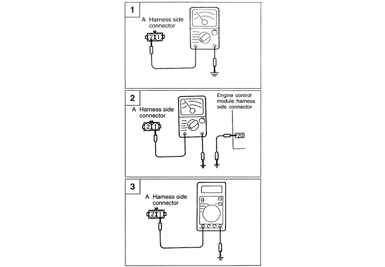
| Fig. 2: The ECT harness testing procedure — 3.0L
(12 valve) engines
|
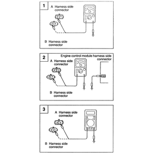
- Unplug the ECT sensor wire connector form the ECT sensor. Check terminal
1, for 2.4L engines, or terminal 2, for all 3.0L and 3.5L engines, of the
connector for continuity to ground. If there is no continuity the problem
lies in the wire harness, repair or replace the harness between the following
terminals:
- 2.4L engines: ECT terminal 1 and ECM terminal 14.
- 3.0L (12 valve) engines: ECT terminal 2 and ECM terminals 17 and 24.
- 3.0L (24 valve) and 3.5L engines: ECT terminal 2 and ECM terminal 72.
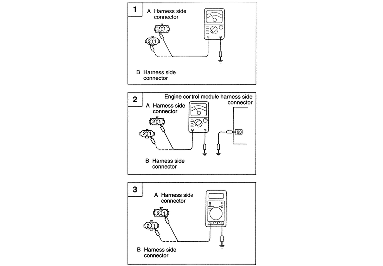
- This step is for all engines except for the 2.4L. Unplug the ECM harness
connector. Check for an open or short circuit between the following ECT sensor
and ECM terminals:
- 3.0L (12 valve) engines: ECT terminal 1 and ECM terminal 20.
- 3.0L (24 valve) and 3.5L engines: ECT terminal 1 and ECM terminal 63.
| Fig. 3: The ECT harness testing procedure — 3.0L
(24 valve) and 3.5L engines
|
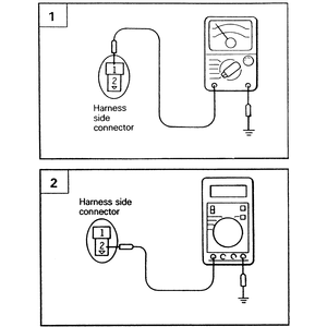
- Make sure the ECM harness connector is plugged in. Turn the ignition switch
to ON and measure the power supply from terminal 2 (2.4L)
or terminal 1 (3.0L and 3.5L) of the ECT harness connector. If the voltage
is not 4.5–4.9 volts, replace the ECM itself, otherwise the harness
and ECM are good.
NOTE: Before replacing the ECM or other computer module,
either check or have the component in question checked.