Each dashboard uses a variety of nuts and bolts of different sizes and lengths.
Correct cataloging and reinstallation is required if the dash is to be free
of annoying squeaks and rattles. Additionally, wires and hoses should be labeled
at the time of removal. The amount of time saved during reassembly makes the
extra effort well worthwhile. Removal of the dash is a complicated, time consuming
task. Do not attempt this procedure if you are not comfortable with extended
projects. Additional helpful information may be found in other parts of this
book dealing with specific assemblies. For example, if not certain how to remove
the radio, refer to "Radio Removal and Installation'' in this section.
- Disconnect the negative battery cable.
- Loosen the tilt wheel lock and lower the wheel to the lowest position.
- Remove the steering wheel.
- Remove the upper and lower steering column covers.
- Remove the instrument cluster. Disconnect the gauge wiring and the speedometer
cable. Once the cluster is out, remove the single screw in the upper center
of the mounting space in the dashboard.
- Remove the radio; disconnect the diesel indicator if so equipped.
- Remove the glove box.
- Remove the floor console and/or center console, depending on equipment
- Remove the screws holding the center air outlet and remove the outlet.
- Remove the ashtray. Remove the two screws holding the ashtray holder. Slide
the holder (bracket) into the dash and remove it.
- Remove the 4 screws from the bottom of the dash. Two are located under the
glovebox opening and two are located approximately under the dash light dimmer
switch on the left side.
- Reach in through the opening in the center of the dash and remove the nut
at the rear of the dash. Make certain you identify the correct nut; it may
be either a wing nut or a hex nut.
- Reach just inside the glovebox opening and remove the screw from the lower
inner surface of the dash.
- From underneath the dash, release the 4 hex nuts holding the upper dash
cover. Once the nuts are off, lift the cover up and off.
- Remove the 5 screws and bolts from the top of the dashboard. Note the location
of each type of fastener.
- Work the dash away from its mounts. Disconnect the wiring harnesses behind
the dash.
- Remove the dash from the car.
To install:
- When reinstalling, place the dash in the car and connect the wiring harnesses,
making certain none are stretched or pinched. Check that the air ducts align
and match correctly.
- Install 5 screws across the top; the screws with the washers go on the ends.
- Fit the upper cover into place and install the nuts from below the dash.
- Install the small screw on the inner lower edge of the glove box.
- Reinstall the nut at the back of the dash.
- Install the lone screw at the upper rear of the instrument cluster area.
- Install the 4 screws, two on each side, across the bottom of the dash.
- Slide the ashtray holder into place and install the screws. Install the
ashtray.
- Install the center air outlet.
- Replace the glove box and tighten the screws.
- Install the radio; connect the diesel indicator wiring if so equipped.
- Install the instrument cluster; connect the wiring and the speedometer cable.
- Install the steering column covers.
- Elevate the tilt column and install the steering wheel.
- Connect the negative battery cable.
- Disconnect the negative battery cable.
- Remove the hazard flasher switch.
- Pop out the hole cover on the right side of the instrument hood.
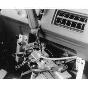
| Fig. 1: Instrument panel (dashboard) removal and
installation components
|
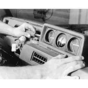
- Remove the instrument hood.
- Remove the instrument cluster, remembering to disconnect the wiring and
speedometer cable at the rear.
| Fig. 2: Remove the four retaining screws to remove
the meter hood
|
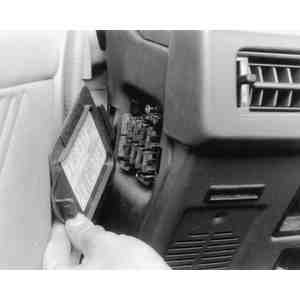
- Remove the fusebox cover. Remove the fusebox from the dashboard and let
it hang.
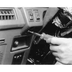
- Remove the glove box. Move the stopper out of the way before lowering the
door.
- Remove the two defroster ducts.
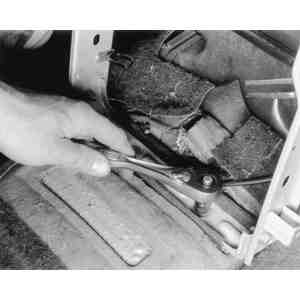
| Fig. 3: To remove the glove box assembly, the glove
box stopper must first be removed
|
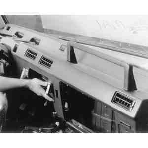
| Fig. 4: Make certain to remove all of the instrument
panel retaining screws before removing the panel
|
- Label and disconnect the 3 control wires running to the heater unit.
- Remove the speaker cover panels on each side.
- Remove the clock or small compartment from the dash.
- Pop out the small square cover at the upper center of the dash. Its easiest
to reach in the clock hole and release the clips with your fingers.
- Remove the lower center faceplate or cover from the center of the dash.
- Remove the shifter knob.
- Remove the floor console assembly.
- Disconnect the left side and front harness connectors running to the dashboard.
- Disconnect the air conditioner and heater wiring harnesses. Disconnect the
instrument cluster harness and the radio connectors, including the antenna
wire.
- Remove the retaining nuts and bolts holding the dash. They are located across
the top, along the sides and at the bottom.
- Use the tilt release lever and move the steering column all the way downward.
- Remove the dash carefully; several components are still connected to it.
To install:
- Place the dash into the vehicle carefully and connect the main electrical
harnesses.
- Install all the retaining nuts and bolts but do not tighten any of them
until the alignment of the dash is correct.
- Reinstall the floor console, the shifter knob and the lower center faceplate.
- Install the upper bolt cover in the center of the dash.
- Replace the clock or small pocket. Don't forget to plug wiring together.
- Install the speaker covers.
- Route the heater control cables properly and connect them. Refer to "Heater
Core Removal and Installation'' for the correct alignment procedure.
- Install the defroster ducts.
- Install the glove box.
- Remount the fusebox on the dash and install the lid.
- Install the instrument cluster. Connect the speedometer cable and wiring
harnesses before tightening the screws.
- Install the instrument cluster hood and install the bolt cover.
- Install the hazard warning switch.
- Connect the negative battery cable.
- Disconnect the negative battery cable.
- Remove the steering wheel.
- Remove the center console.
- Remove the meter assembly. Carefully disconnect the wiring and speedometer
cable.
- Remove the gauge assembly and disconnect its wiring.
- Remove the lap heater ducts below the dash and disconnect the release cable
bracket from the dash.
- Remove the heater control assembly. Label each cable as it is disconnected
at the heater end.
- Remove the fuse cover on the side of the dash. unscrew the mounting bolts
and push the fuseblock into the dashboard.
- Disconnect the wiring from the front speakers.
- Remove the plug at the center of the instrument panel.
- Remove the right and left side defroster grilles by gently prying on the
mounting projections with a small flat tool. Be careful not to break the projections
off.
- Remove the glove box.
- Disconnect the wiring from the heater relay.
- Remove the mounting nuts and bolts and remove the instrument panel.
To install:
- Reinstall the dashboard and secure the mounting bolts.
- Connect the heater relay wiring and install the glove box.
- Install the side defroster grilles and the plug at the center of the dash.
- Connect the front speaker wiring.
- Position the fusebox and install its screws; install the cover.
- Install the heater control assembly and connect the control cables. Refer
to "Heater Core Removal and Installation'' for correct alignment of the cables.
- Install the two lap heater ducts and install the hood release cable bracket.
- Install the combination gauge unit and connect the wiring.
- Install the instrument cluster. Connect the wiring and the speedometer cable.
- Install the center console.
- Install the steering wheel.
- Connect the negative battery cable.
CAUTION
If removal of the steering wheel on a vehicle equipped with an air bag is planned,
refer to the Supplemental Restraint System procedures in this Section 6 for
instructions and warnings
- Disconnect the negative battery cable.
- Remove the lap heater air ducts under the left and right side dash.
- Remove the hood release cable bracket from the dashboard.
- Remove the left and right side defroster grilles. Use a small flat tool
to raise the attaching projections. Don't break the tabs.
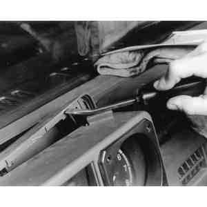
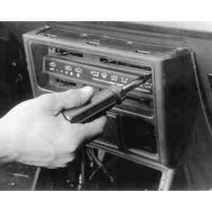
| Fig. 5: Use a prytool and a piece of rubber or a
rag to remove the cluster rear cover
|
| Fig. 6: Remove the fuse box cover and the fuse box
itself
|
| Fig. 7: Remove the retaining screws securing the
instrument cluster
|
| Fig. 8: Removing the combination meter case from
the instrument panel — 1987–91 Monteros
|
- Remove the glove box.
- Use a flat, padded tool to remove the rear cover from the instrument cluster.
- Remove the instrument cluster. Disconnect the speedometer cable and the
wiring harnesses to the back of the cluster.
- Disconnect the wiring to each switch on the cluster. Label each as it is
removed.
- Remove the screws from the side of the combination meter unit and remove
the cover.
- Remove the 4 screws at the base of the combination meter and gently remove
the meter. Disconnect the wire harnesses.
| Fig. 9: The center panel and all of its components
will have to also be removed
|
WARNING
The inclinometer can be damaged by dropping or bumping it. Do not tilt the
unit so far as to exceed the maximum indication on the scale. Resist the
temptation to play with the unit.
- Remove the center panel or lower console.
- Disconnect the 3 heater control cables running to the heater unit. Label
each one.
| Fig. 10: Unhook the heater control assembly cables
from the heater control levers
|
- Remove the center reinforcement and bring it out as a unit with the radio
or stereo. Disconnect the wiring when the unit is free.
| Fig. 11: Remove all of the mounting bolts from the
center reinforcement, then remove the reinforcement itself
|
| Fig. 12: After removing all of its mounting screws,
remove the instrument panel from the vehicle
|
- Remove the horn pad and remove the steering wheel.
- Remove the fuse box cover and release the fusebox from the dashboard.
- Remove the dashboard mounting nuts and bolts and remove the dashboard.
To install:
- When reinstalling, position the dash and start each nut and bolt. Make certain
the dash is aligned and then tighten the fittings.
- Install the fusebox assembly and its cover.
- Install the steering wheel and horn pad.
- Install the radio and center reinforcement. Connect the wiring before tightening
the bolts.
- Carefully route and connect the heater control cables. Refer to "Heater
Core Removal and Installation'' for correct alignment of the cables.
- Install center panel and secure the heater controls.
- Install the combination gauges and connect the wiring.
- Install the cover for the combination gauges.
- Install the instrument cluster, connecting the speedometer cable and the
many wiring connectors.
- Install the cluster cover; make sure it is firmly seated in place.
- Replace the glove box
- Reinstall the side defroster grilles.
- Connect the hood release cable bracket.
- Install the two lap heater ducts.
- Connect the negative battery cable.
CAUTION
When installing or removing the instrument panel, do not allow any impact or
shock to the SRS diagnosis unit. Always disable the SRS system when working
on or near the SRS components. Refer to Section 6 for SRS precautions.
- Disconnect the negative (-) battery cable from the battery.
- Wait at least 60 seconds after disconnecting the battery cable to make certain
that the SRS is completely disarmed before servicing the vehicle.
- Remove the floor console.
- Remove the hood lock release and the fuel filler door lock release handles.
- Loosen and remove the retaining screws, then the instrument under and corner
covers.
| Fig. 13: Floor console removal and installation component
locations — 1992–95 Monteros
|
| Fig. 14: Instrument panel removal and installation
component locations — 1992–95 Monteros
|
- Remove the glove box stopper and then the glove box.
- Unscrew the mounting screws and remove the center panel A.
- Extract the heater control assembly.
- Take the radio and tape player out.
- Pop the meter hood plug out, then remove the meter bezel assembly by loosening
and removing the mounting screws.
- Remove the screws holding the combination meter (instrument cluster) in
place and extract the meter.
- Disconnect and remove the speedometer cable adapter. First disconnect the
speedometer cable at the transmission end of the cable, then remove the lock
of the speedometer cable adapter from the instrument panel. Pull the speedometer
cable slightly toward the vehicle interior, then remove the speedometer cable
adapter.
- Remove the four screws holding the column cover in place, then remove the
cover itself.
- Remove the clock or clock plug.
- Remove the side defroster garnish, the door mirror control switch, the front
speaker, the rheostat, the rear wiper and washer switch and the door lock
switch.
- Disconnect the ventilation control wire and the wiring harness.
- Unscrew the steering column installation bolts.
- Unscrew all the retaining screws holding the dashboard (instrument panel
assembly) in place and remove the assembly.
To install:
- Hold the instrument panel the assembly in position and secure it in place
with its mounting screws.
- Tighten the steering column installation bolts and plug the harness connector
back together.
- To install the ventilation control wire, set the cool air bypass dial to
the closed position. Close the cool air bypass lever at the heater unit side
(lever is lightly hit against the stopper). Install the ventilation control
wire and secure it with the clip.
- Install the door lock switch, the rear wiper and washer switch, the rheostat,
the front speaker, the door mirror control switch, the side defroster garnish,
the clock or clock plug and the column cover.
- Hook the speedometer cable adapter back up the back of the combination meter
(instrument cluster).
- Install the combination meter, the meter bezel assembly and the meter hood
plug.
- hook the radio and tape player back up and install them in the dashboard.
- Install the heater control assembly, center panel A, the glove box assembly
and the glove box stopper.
- Install the instrument under and corner covers, the fuel filler door lock
release handle and the hood lock release handle.
- Install the floor console.
- Connect the negative (-) battery cable to the battery and enable the SRS.