|
Q.
Is the check result normal?
 Go to Step 2. Go to Step 2.
 Repair the defective connector. Repair the defective connector.
|
|
|
Q.
Is the check result normal?
|
|
|
Replace the front right wheel speed sensor (Refer to  ). ).
|
|
|
|
|
Q.
Is the check result normal?
Go to Step 4.
Repair the defective connector.
|
|
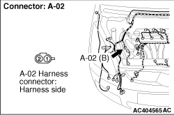
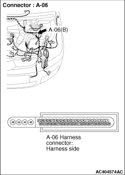
(1)Disconnect the A-02 front right wheel speed sensor Connector and A-06 ABS/Active
stability control system-ECU connector, and connect special tool ABS Check Harness (MB991984)
to the wiring harness-side connector.
| note |
Do not connect special tool ABS Check Harness (MB991984) to the ABS/Active stability
control system-ECU.
|
|
|
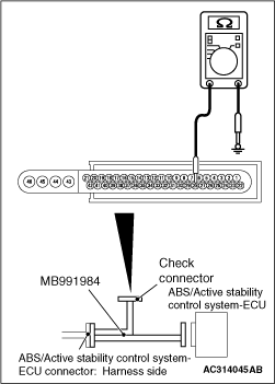
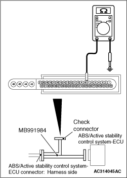
(2)Resistance between special tool ABS Check Harness (MB991984) connector terminal No.28
and body earth
OK: Open circuit or more than 1 kΩ
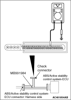
(3)Turn the ignition switch to the "ON" position.
|
|
(4)Voltage between special tool ABS Check Harness (MB991984) connector terminal No.28 and
body earth
OK: 0 V
(5)Turn the ignition switch to the "OFF" position.
|
|
(6)Resistance between special tool ABS Check Harness (MB991984) connector terminal No.29
and body earth
OK: Open circuit or more than 1 kΩ
Q.
Are the check result normal?
Go to Step 5.
Repair the wiring harness between A-06 ABS/Active stability control system-ECU
connector terminal Nos. 28 or 29 and A-02 front right wheel speed sensor connector terminal
No.1 or 2.
|
|
(1)Disconnect the A-02 front right wheel speed sensor Connector and A-06 ABS/Active
stability control system-ECU connector, and connect special tool ABS Check Harness (MB991984)
to the wiring harness-side connector.
| note |
Do not connect special tool ABS Check Harness (MB991984) to the ABS/Active stability
control system-ECU.
|
|
|
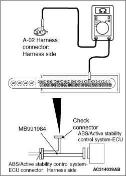
(2)Resistance between special tool ABS Check Harness (MB991984) connector terminal 28 and
A-02 front right wheel speed Sensor Connector terminal 1
OK: 10 Ω or less
|
|
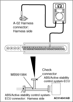
(3)Resistance between special tool ABS Check Harness (MB991984) connector terminal 29 and
A-02 front right wheel speed sensor connector terminal 2
OK: 10 Ω or less
Q.
Is the check result normal?
Go to Step 6.
Repair the wiring harness between A-06 ABS/Active stability control system-ECU
connector terminal Nos. 28 or 29 and A-02 front right wheel speed sensor connector terminal
No.1 or 2.
|
|
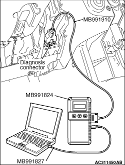
| caution |
Before connecting or disconnecting the M.U.T.-III, turn the ignition switch to the "LOCK"
(OFF) position.
|
Check again if the diagnosis code is set.
(1)Turn the ignition switch to the "ON" position.
(2)Erase the diagnosis code.
(3)Turn the ignition switch to the "LOCK" (OFF) position.
(4)Turn the ignition switch to the "ON" position.
(5)Check if the diagnosis code is set.
(6)Turn the ignition switch to the "LOCK" (OFF) position.
(7)Disconnect M.U.T.-III.
Q.
Is code No.C1200 set?
Replace the hydraulic unit (integrated with ABS/Active stability control
system-ECU). Then perform the variant coding and write the VIN data (Refer to GROUP 00, Precautions
Before Service - How to Perform Variant Coding ).
The trouble can be an intermittent malfunction (Refer to GROUP 00 - How
to use Troubleshooting/inspection Service Points - How to Cope with Intermittent
Malfunction ).
|
)
)
)
)
)
)
)
)
)