|
|
(3)Measure the voltage between the battery terminals.
OK: more than 9 V
|
|
|
Q.
Is the check result normal?
|
|
|
 Diagnose the charging system (Refer to GROUP 16, Charging System - On-vehicle
Service Diagnose the charging system (Refer to GROUP 16, Charging System - On-vehicle
Service  ). ).
|
|
|
|
|
Q.
Are the check result normal?
 Go to Step 3. Go to Step 3.
Repair the defective connector.
|
|
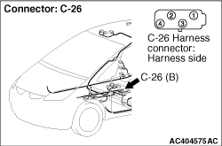
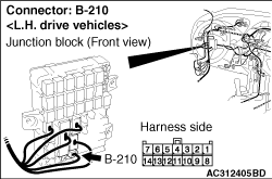
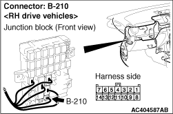
(1)Disconnect the C-26 G and yaw rate sensor connector, and connect B-210 junction block
connector.
|
|
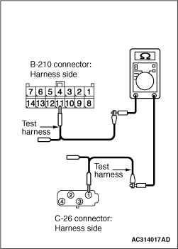
(2)Resistance between C-26 G and yaw rate sensor connector terminal No.1 and B-210 junction
block connector terminal No.11
OK: Less than 5 Ω
Q.
Is the check result normal?
Go to Step 4.
Repair the wiring harness.
|
|
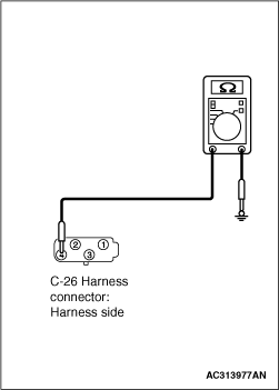
(1)Disconnect the C-26 G and yaw rate sensor connector, and connect special tool test Harness
to the wiring harness-side connector.
| note |
Connect the special tool Test Harness to the ABS/Active stability control system-ECU.
|
|
|
(2)Resistance between C-26 G and yaw rate sensor connector terminal No.4 and body earth
OK: 5 Ω or less
Q.
Is the check result normal?
Go to Step 5.
Repair the wiring harness.
|
|
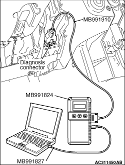
| caution |
Before connecting or disconnecting the M.U.T.-III, turn the ignition switch to the "LOCK"
(OFF) position.
|
Check again if the diagnosis code is set.
(1)Turn the ignition switch to the "ON" position.
(2)Erase the diagnosis code.
(3)Turn the ignition switch to the "LOCK" (OFF) position.
(4)Turn the ignition switch to the "ON" position.
(5)Check if the diagnosis code is set.
(6)Turn the ignition switch to the "LOCK" (OFF) position.
(7)Disconnect M.U.T.-III.
Q.
Is code No.C1863 set?
Replace the G and yaw rate sensor.
The trouble can be an intermittent malfunction (Refer to GROUP 00 - How
to use Troubleshooting/inspection Service Points - How to Cope with Intermittent
Malfunction ).
|
)
)
)
)
)
)
)