Code No. C1456: Wiring harness or coupling coil overcurrent failure
|
| caution |
If there is any problem in the CAN bus lines, an incorrect diagnosis code may be set. Prior to this diagnosis, always diagnose the CAN bus lines.
|
|
OPERATION
The current flowing the coupling coil is monitored, and if it exceeds the specified value, the system is deactivated.
DIAGNOSIS CODE SET CONDITIONS
If the following conditions are met when the system is in operation (always), 4WD-ECU switches the control from 4WD to 2WD, flashes the 4WD/LOCK indicators alternately, and sets the diagnosis code No. C1456.
- Electronic control coupling solenoid current monitor value: 6 A or more (deviated from the normal current value range)
PROBABLE CAUSES
Current trouble
- Damaged harness wires and connector (Short to earth between 4WD-ECU and the electronic control coupling solenoid)
- 4WD-ECU internal error
- Short circuit in the coupling coil
Past trouble
- Intermittent wiring harness or connector failure
| note |
For diagnosis procedures, refer to "How to treat past trouble" (Refer to GROUP 00 - How to Use Troubleshooting/How to Treat Past Trouble  ). ).
|
- Intermittent electronic control coupling failure (solenoid failure)
|
|
STEP 1. M.U.T.-III CAN bus diagnostics
|
|
|
Use M.U.T.-III to diagnose the CAN bus lines.
|
|
|
Q.
Is the check result normal?
|
|
|
 Go to Step 3. Go to Step 3.
|
|
|
|
|
|
 Repair the CAN bus line (Refer to GROUP 54C - Troubleshooting/CAN Bus Diagnostics Table ). On completion, go to Step 2. Repair the CAN bus line (Refer to GROUP 54C - Troubleshooting/CAN Bus Diagnostics Table ). On completion, go to Step 2.
|
|
|
|
|
|
STEP 2. Check whether the diagnosis code is reset after repairing the CAN bus line.
|
|
|
(1)Erase the diagnosis code.
|
|
|
(2)Turn the ignition switch from the "LOCK" (OFF) position to the "ON" position.
|
|
|
(3)Fully depress the accelerator pedal, and maintain its position for 2 seconds.
| note |
The coupling coil electronic control is also based on the accelerator pedal opening degree, thus the signal is sent to the ECU.
|
|
|
|
(4)Check if the diagnosis code is set.
|
|
|
Q.
Is the diagnosis code No. C1456 set?
|
|
|
Go to Step 3.
|
|
|
|
|
|
This diagnosis is complete.
|
|
|
|
|
|
STEP 3. M.U.T.-III data list
|
|
|
Check the following data list (Refer to ).
|
|
|
- Item 04: Desired current of coupling
- Item 05: Monitored current of coupling
|
|
|
Q.
Is the check result normal?
|
|
|
Go to Step 10.
|
|
|
|
|
|
Go to Step 4.
|
|
|
|
|
|
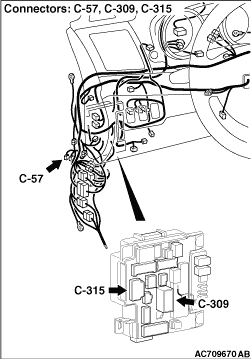
STEP 4. Check the following connector:
|
|
|
Check the connectors below for improper engagement, terminal damage or terminal drawn in the connector case.
|
|
|
- C-57 4WD-ECU connector
- D-39 intermediate connector
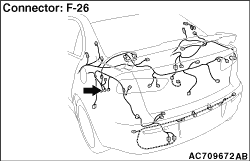
- F-26 electronic control coupling solenoid connector
- C-27 intermediate connector
|
|
|
Q.
Are the connectors and terminals in good condition?
|
|
|
Go to Step 5.
|
|
|
|
|
|
Repair the connector(s) or terminal(s). Then go to Step 11.
|
|
|
|
|
|
STEP 5. Wiring harness check
|
|
|
Check the wiring harness between the C-57 4WD-ECU connector and the F-26 electronic control coupling solenoid connector, and the wiring harness between the F-26 electronic control coupling solenoid connector and the F-26-1 electronic control coupling solenoid side connector for damage or other problem.
|
|
|
Q.
Is the wiring harness in good condition?
|
|
|
Go to Step 6.
|
|
|
|
|
|
Repair damage or other problem in the wiring harness. Then go to Step 11.
|
|
|
|
|
|
STEP 6. Resistance measurement between electronic control coupling solenoid connector terminals
|
|
|
Disconnect the F-26-1 connector, and measure the resistance value between the connector terminals on the electronic control coupling side.
|
|
|
Standard value: 2.2 - 4.0 Ω
|
|
|
Q.
Is the measured resistance value within the standard value range?
|
|
|
Go to Step 7.
|
|
|
|
|
|
Replace the electronic control coupling (Refer to ). Then go to Step 11.
|
|
|
|
|
|
STEP 7. Voltage measurement at the 4WD-ECU connector
|
|
|
(1)Disconnect the C-57 4WD-ECU connector.
|
|
|
(2)Measure the voltage between the C-57 wiring harness side connector terminals No.3, No.4 (ignition switch "ON") and the body earth.
OK: System voltage
|
|
|
Q.
Is the check result normal?
|
|
|
Go to Step 8.
|
|
|
|
|
|
Go to Step 9.
|
|
|
|
|
|
STEP 8. Wiring harness check
|
|
|
Check the wiring harness between the C-57 4WD-ECU connector (terminal No.10) and the body earth for damage or other problem.
|
|
|
Q.
Is the wiring harness in good condition?
|
|
|
Go to Step 10.
|
|
|
|
|
|
Repair the wiring harness. Then go to Step 11.
|
|
|
|
|
|
STEP 9. Wiring harness check
|
|
|
| note |
Prior to the wiring harness inspection, check the C-309 and C-315 ETACS-ECU connectors, and repair if necessary.
|
|
|
|
Check the wiring harness between the C-57 4WD-ECU connector (terminal No.3) and the fusible link No. 34, and the wiring harness between the C-57 4WD-ECU connector [terminal No.4 (ignition switch "ON")] and the fusible link No. 34 for damage or other problem.
|
|
|
Q.
Is the wiring harness in good condition?
|
|
|
Go to Step 10.
|
|
|
|
|
|
Repair the wiring harness. Then go to Step 11.
|
|
|
|
|
|
STEP 10. Check whether the diagnosis code is reset.
|
|
|
(1)Erase the diagnosis code.
|
|
|
(2)Turn the ignition switch from the "LOCK" (OFF) position to the "ON" position.
|
|
|
(3)Fully depress the accelerator pedal, and maintain its position for 2 seconds.
| note |
The coupling coil electronic control is also based on the accelerator pedal opening degree, thus the signal is sent to the ECU.
|
|
|
|
(4)Check if the diagnosis code is set.
|
|
|
Q.
Is the diagnosis code No. C1456 set?
|
|
|
Replace 4WD-ECU (Refer to ) Then go to Step 11
.
|
|
|
|
|
|
The trouble can be an intermittent malfunction (Refer to GROUP 00 - How to Use Troubleshooting/How to Cope with Intermittent Malfunction ).
|
|
|
|
|
|
STEP 11. Check whether the diagnosis code is reset.
|
|
|
Q.
Is the diagnosis code No. C1456 set?
|
|
|
Diagnose again from Step 1.
|
|
|
|
|
|
This diagnosis is complete.
|
|
|
|
)
)
)