Code No.C1513 Torque sensor power supply
|
|
| caution |
- If there is any problem in the CAN bus lines, an incorrect diagnosis code may be set. Prior to this diagnosis, diagnose the CAN bus lines.
- Whenever ECU is replaced, ensure that the CAN bus lines are normal.
|
|
|
|
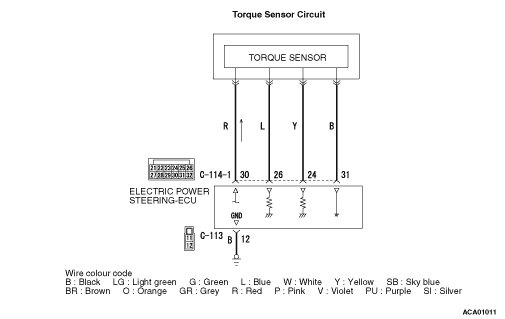
- Power is supplied to the electric power steering-ECU from the torque sensor.
|
|
|
- To output the voltage based on the input torque from the torque sensor to the electric power steering-ECU, the voltage is supplied to the torque sensor.
|
|
|
Check Conditions
- With the battery voltage exceeding 7.5 V, the torque sensor power supply turns ON.
|
|
|
Judgement Criterion
- The torque sensor power supply voltage is more than 5.3 V or less than 4.7 V.
- The torque sensor power supply monitor voltage does not meet a predetermined voltage stored in the microcomputer, and the microcomputer determines that there is a problem in the torque sensor power supply voltage.
|
|
|
Fail Safe, Back Up Function
- The electric power steering-ECU stops the motor control and illuminates the electric power steering warning display, then sets the diagnosis code No. C1513.
|
|
|
- Malfunction of CAN bus line
- Defective torque sensor of the steering gear and linkage assembly
- Defective harness wire(s) or connector(s)
- Short or open circuit between the electric power steering-ECU and the torque sensor or loose connector contact
- Open circuit between the body earth and the electric power steering-ECU or loose connector contact
- Malfunction of the electric power steering-ECU
|
|
|
STEP 1. M.U.T.-III CAN bus diagnostics
|
|
|
Use M.U.T.-III to diagnose the CAN bus lines.
|
|
|
Q.
Is the check result normal?
|
|
|
 Go to Step 3. Go to Step 3.
|
|
|
|
|
|
 Repair the CAN bus lines (Refer to GROUP 54C - Troubleshooting/CAN Bus Diagnostics Table Repair the CAN bus lines (Refer to GROUP 54C - Troubleshooting/CAN Bus Diagnostics Table  ). On completion, go to Step 2. ). On completion, go to Step 2.
|
|
|
|
|
|
STEP 2. Diagnosis code recheck after resetting CAN bus lines
|
|
|
(1)Erase the diagnosis code.
|
|
|
(2)Turn the ignition switch from the "LOCK" (OFF) position to the "ON" position.
|
|
|
(3)Check if the diagnosis code is set.
|
|
|
Q.
Is the diagnosis codes C1513 set?
|
|
|
Go to Step 3.
|
|
|
|
|
|
This diagnosis is complete.
|
|
|
|
|
|
STEP 3. Check the following connector.
|
|
|
Check the connectors below for improper engagement, terminal damage or terminal drawn in the connector case.
|
|
|
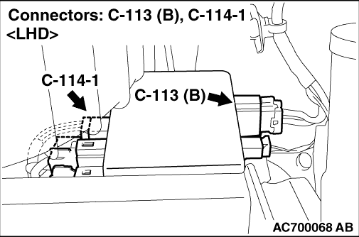
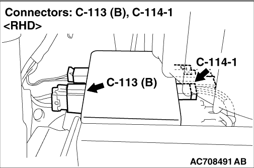
- C-113 and C-114-1 electric power steering-ECU connector
- Body earth point
- Torque sensor intermediate connector of the wiring harness for steering gear box & linkage assembly (connection and appearance checks only)
|
|
|
Q.
Is the connectors and terminals in good condition?
|
|
|
Go to Step 4.
|
|
|
|
|
|
Replace the steering gear and linkage assembly (Refer to ). Then go to Step 8.
|
|
|
|
|
|
STEP 4. Wiring harness check
|
|
|
(1)Check the wiring harness between the C-114-1 electric power steering-ECU connector terminals No.30 or No.31 and the torque sensor for damage or other problem .
|
|
|
(2)Check the wiring harness between the C-113 electric power steering-ECU connector terminal No.12 and the body earth point for damage or other problem .
|
|
|
Q.
Is the wiring harness in good condition?
|
|
|
Go to Step 5.
|
|
|
|
|
|
Replace the steering gear and linkage assembly (Refer to ). Then go to Step 8.
|
|
|
|
|
|
STEP 5. Voltage measurement at the electric power steering-ECU connector
|
|
(1)The steering is in the neutral position.
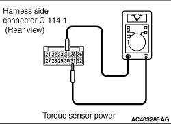
(2) Measure the electric power steering-ECU voltage without disconnecting the connector (by backprobing).
(3)Turn the ignition switch from the "LOCK" (OFF) position to the "ON" position.
(4)Measure the voltage between the C-114-1 electric power steering-ECU connector terminal No.30 and No.31.
OK: 5±0.2 V
Q.
Is the check result normal?
Go to Step 6.
Replace the Steering gear and linkage assembly (Refer to ).Then go to Step 8.
|
|
|
STEP 6. M.U.T.-III data list
|
|
|
(1)The steering is in the neutral position.
|
|
|
(2)Check the following data list .
- Item No. 03: Torque sensor(power supply)
|
|
|
Q.
Is the check result normal?
|
|
|
Go to Step 8.
|
|
|
|
|
|
Go to Step 7.
|
|
|
|
|
|
STEP 7. Check whether the diagnosis code is reset.
|
|
|
(1)Erase the diagnosis code.
|
|
|
(2)Turn the ignition switch from the "LOCK" (OFF) position to the "ON" position.
|
|
|
(3)Check if the diagnosis code is set.
|
|
|
Q.
Is the diagnosis codes C1513 set?
|
|
|
Replace the electric power steering-ECU (Refer to ).Then go to Step 8.
|
|
|
|
|
|
Intermittent malfunction (Refer to GROUP 00 - How to Use Troubleshooting/How to Cope with Intermittent Malfunction ).
|
|
|
|
|
|
STEP 8. Check whether the diagnosis code is reset.
|
|
|
(1)Erase the diagnosis code.
|
|
|
(2)Turn the ignition switch from the "LOCK" (OFF) position to the "ON" position.
|
|
|
(3)Check if the diagnosis code is set.
|
|
|
Q.
Is the diagnosis codes C1513 set?
|
|
|
Return to Step 1.
|
|
|
|
|
|
This diagnosis is complete.
|
|
|
|
)
)
)
)