Code No.C1530 Motor FET driver
Code No.C1531 Motor current too low
Code No.C1532 Motor output current too large
Code No.C1533 Motor terminal initial voltage
Code No.C1534 Motor terminal monitor voltage
Code No.C1535 Motor output current
Code No.C1536 Motor terminal voltage abnormality (high voltage)
|
|
| caution |
- If there is any problem in the CAN bus lines, an incorrect diagnosis code may be set. Prior to this diagnosis, diagnose the CAN bus lines.
- Whenever ECU is replaced, ensure that the CAN bus lines are normal.
|
|
|
|
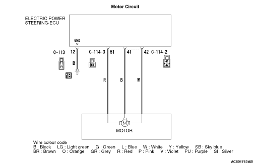
- Power is supplied to the motor from the electric power steering-ECU.
|
|
|
- The voltage controlled by the torque sensor and resolver is supplied to the motor from the electric power steering-ECU.
|
|
|
Check Conditions
- The motor voltage is in between 0 V and the battery voltage.
|
|
|
Judgement Criterion
- The motor voltage does not meet a predetermined voltage stored in the microcomputer, and the microcomputer determines that there is a problem in the motor system.
|
|
|
Fail Safe, Back Up Function
- The electric power steering-ECU stops the motor control and illuminates the electric power steering warning display, then sets the diagnosis code Nos. C1530, C1531, C1532, C1533, C1534, C1535, and C1536.
|
|
|
- Malfunction of CAN bus line
- Defective motor of the steering gear and linkage assembly
- Defective harness wire(s) or connector(s)
- Short or open circuit between the electric power steering-ECU and the motor or loose connector contact
- Open circuit between the body earth and the electric power steering-ECU or loose connector contact
- Malfunction of the electric power steering-ECU
|
|
|
STEP 1. M.U.T.-III CAN bus diagnostics
|
|
|
Use M.U.T.-III to diagnose the CAN bus lines.
|
|
|
Q.
Is the check result normal?
|
|
|
 Go to Step 3. Go to Step 3.
|
|
|
|
|
|
 Repair the CAN bus lines (Refer to GROUP 54C - Troubleshooting/CAN Bus Diagnostics Table Repair the CAN bus lines (Refer to GROUP 54C - Troubleshooting/CAN Bus Diagnostics Table  ). On completion, go to Step 2 ). On completion, go to Step 2
|
|
|
|
|
|
STEP 2. Diagnosis code recheck after resetting CAN bus lines
|
|
|
(1)Erase the diagnosis code.
|
|
|
(2)Turn the ignition switch from the "LOCK" (OFF) position to the "ON" position.
|
|
|
(3)Check if the diagnosis code is set.
|
|
|
Q.
Is the diagnosis codes C1530,C1531,C1532,C1533,C1534,C1535 or C1536 set?
|
|
|
Go to Step 3.
|
|
|
|
|
|
This diagnosis is complete.
|
|
|
|
|
|
STEP 3. Check the following connector.
|
|
|
Check the connectors below for improper engagement, terminal damage or terminal drawn in the connector case.
|
|
|
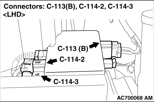
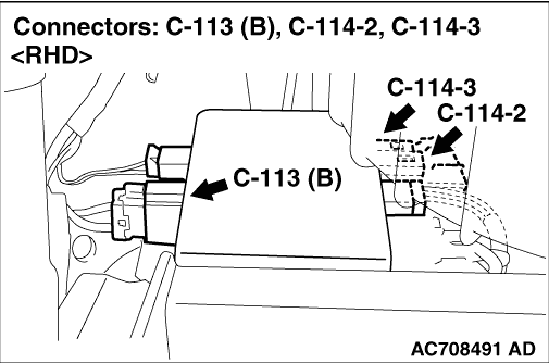
- C-113, C-114-2 and C-114-3 electric power steering-ECU connector
- Body earth point
|
|
|
Q.
Is the connectors and terminals in good condition?
|
|
|
Go to Step 4.
|
|
|
|
|
|
Replace the steering gear and linkage assembly (Refer to ). Then go to Step 8.
|
|
|
|
|
|
STEP 4. Wiring harness check
|
|
|
(1)Check the wiring harness between the C-114-2 electric power steering-ECU connector terminals No.41 or No.42 and the motor for damage or other problem .
|
|
|
(2)Check the wiring harness between the C-114-3 electric power steering-ECU connector terminal No.51 and the motor for damage or other problem .
|
|
|
(3)Check the wiring harness between the C-113 electric power steering-ECU connector terminal No.12 and the body earth point for damage or other problem .
|
|
|
Q.
Is the wiring harness in good condition?
|
|
|
Go to Step 5.
|
|
|
|
|
|
Replace the steering gear and linkage assembly (Refer to ). Then go to Step 8.
|
|
|
|
|
|
STEP 5. M.U.T.-III data list
|
|
|
Check the following data list .
|
|
|
- Item No. 04: Motor current
- Item No. 05: Motor current (target)
- Item No. 16: Motor current (unlimited target)
- Item No. 17: Motor electric angle
- Item No. 18: Motor speed
- Item No. 19: Motor voltage
- Item No. 25: Motor relay
- Item No. A12: Motor current (target) :rec.A1
- Item No. A13: Motor cur. (unltd target) :rec.A1
- Item No. A14: Motor current :rec.A1
- Item No. A22: Motor current (target) :rec.A2
- Item No. A23: Motor cur. (unltd target) :rec.A2
- Item No. A24: Motor current :rec.A2
- Item No. A32: Motor current (target) :rec.A3
- Item No. A33: Motor cur. (unltd target) :rec.A3
- Item No. A34: Motor current :rec.A3
- Item No. A42: Motor current (target) :rec.A4
- Item No. A43: Motor cur. (unltd target) :rec.A4
- Item No. A44: Motor current :rec.A4
- Item No. A52: Motor current (target) :rec.A5
- Item No. A53: Motor cur. (unltd target) :rec.A5
- Item No. A54: Motor current :rec.A5
- Item No. B12: Power relay voltage :rec V1
- Item No. B22: Power relay voltage :rec V2
- Item No. B32: Power relay voltage :rec V3
- Item No. B42: Power relay voltage :rec V4
- Item No. B52: Power relay voltage :rec V5
|
|
|
Q.
Is the check result normal?
|
|
|
Go to Step 8.
|
|
|
|
|
|
Go to Step 6.
|
|
|
|
|
|
STEP 6. Check whether the diagnosis code is reset.
|
|
|
(1)Erase the diagnosis code.
|
|
|
(2)Turn the ignition switch from the "LOCK" (OFF) position to the "ON" position.
|
|
|
(3)Check if the diagnosis code is set.
|
|
|
Q.
Is the diagnosis codes C1530,C1531,C1532,C1533,C1534,C1535 or C1536 set?
|
|
|
Replace the electric power steering-ECU (Refer to ).Then go to Step 7.
|
|
|
|
|
|
Intermittent malfunction (Refer to GROUP 00 - How to Use Troubleshooting/How to Cope with Intermittent Malfunction ).Then go to Step 7.
|
|
|
|
|
|
STEP 7. Check whether the diagnosis code is reset.
|
|
|
(1)Erase the diagnosis code.
|
|
|
(2)Turn the ignition switch from the "LOCK" (OFF) position to the "ON" position.
|
|
|
(3)Check if the diagnosis code is set.
|
|
|
Q.
Is the diagnosis codes C1530,C1531,C1532,C1533,C1534,C1535 or C1536 set?
|
|
|
Replace the steering gear and linkage assembly (Refer to ).Then go to Step 8.
|
|
|
|
|
|
Intermittent malfunction (Refer to GROUP 00 - How to Use Troubleshooting/How to Cope with Intermittent Malfunction ).
|
|
|
|
|
|
STEP 8. Check whether the diagnosis code is reset.
|
|
|
(1)Erase the diagnosis code.
|
|
|
(2)Turn the ignition switch from the "LOCK" (OFF) position to the "ON" position.
|
|
|
(3)Check if the diagnosis code is set.
|
|
|
Q.
Is the diagnosis codes C1530,C1531,C1532,C1533,C1534,C1535 or C1536 set?
|
|
|
Return to Step 1.
|
|
|
|
|
|
This diagnosis is complete.
|
|
|
|
)
)
)