Code No. B2513
Levelling actuator output error
| caution |
Before replacing the ECU, ensure
that the power supply circuit, the earth circuit and the communication circuit are normal.
|
DIAGNOSTIC FUNCTION
If a trouble occurs in headlamp assembly (headlamp levelling unit), headlamp automatic
levelling system warnings are displayed on the multi information display and code No. B2513
is stored.
JUDGEMENT CRITERIA
The headlamp automatic levelling-ECU detects the short-circuit of the signal line to the
headlamp levelling unit for 1 second or longer continuously.
PROBABLE CAUSES
- Malfunction of headlamp assembly (headlamp levelling
unit)
- Malfunction of the headlamp automatic levelling-ECU
- Damaged harness wires and connectors
DIAGNOSIS PROCEDURE
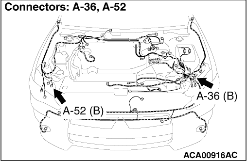
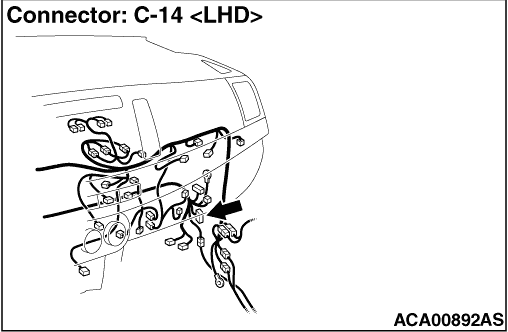
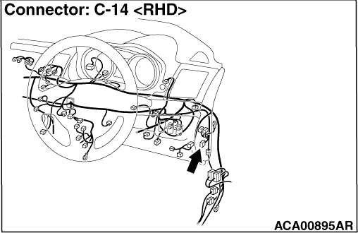
STEP 1. Connector check: A-36 headlamp assembly (LH) connector,
C-14 headlamp automatic levelling-ECU connector
Q.
Is the check result normal?
 Go to Step 2.
 Repair the defective connector.
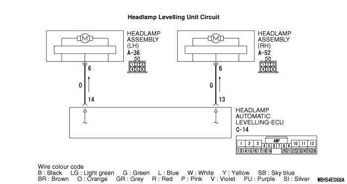
STEP 2. Wiring harness check between the A-36 headlamp assembly (LH)
connector terminal No. 6 and the C-14 headlamp automatic levelling-ECU connector terminal No.
14
- Check the signal lines for short circuit.
Q.
Is the check result normal?
Go to Step 3.
Repair the wiring harness.
STEP 3. Check whether the diagnosis code is reset.
Q.
Is diagnosis code No. B2513 set?
Go to Step 4.
The trouble can be an intermittent malfunction (Refer to GROUP 00 - How
to use Troubleshooting/inspection Service Points - How to cope with Intermittent Malfunction  ).
).
STEP 4. Connector check: A-52 headlamp assembly (RH) connector
Q.
Is the check result normal?
Go to Step 5.
Repair the defective connector.
STEP 5. Wiring harness check between the A-52 headlamp assembly (RH)
connector terminal No. 6 and the C-14 headlamp automatic levelling-ECU connector terminal No.
13
- Check the signal lines for short circuit.
Q.
Is the check result normal?
Go to Step 6.
Repair the wiring harness.
STEP 6. Check whether the diagnosis code is reset.
Q.
Is diagnosis code No. B2513 set?
Go to Step 7.
The trouble can be an intermittent malfunction (Refer to GROUP 00 - How
to use Troubleshooting/inspection Service Points - How to cope with Intermittent Malfunction ).
STEP 7. M.U.T.-III data list
|
|
(1)Disconnect the headlamp assembly (LH) and (RH) connector.
|
|
|
(2)Turn the ignition switch from "LOCK" (OFF) position to "ON" position.
|
|
Item No.
|
Item name
|
Normal condition
|
Item 68
|
A/L actuator output voltage
|
Indicates the voltage value of system voltage within the range of
20 to 80%.
|
|
OK: Normal condition is displayed.
|
Q.
Is the check result normal?
Go to Step 8.
Replace the headlamp automatic levelling-ECU.
STEP 8. Check the headlamp assembly (LH).
Check the headlamp assembly (LH) for internal failure.
|
|
(1)Disconnect the headlamp assembly (RH) connector.
|
|
|
(2)Turn the ignition switch from "LOCK" (OFF) position to "ON" position.
|
|
|
(3)Perform the drive test using the M.U.T.-III. Refer to .
|
Q.
Is the check result normal?
Go to Step 9.
Replace the headlamp assembly (LH).
STEP 9. Check the headlamp assembly (RH).
Check the headlamp assembly (RH) for internal failure.
|
|
(1)Disconnect the headlamp assembly (LH) connector.
|
|
|
(2)Turn the ignition switch from "LOCK" (OFF) position to "ON" position.
|
|
|
(3)Perform the drive test using the M.U.T.-III. Refer to .
|
Q.
Is the check result normal?
Replace the headlamp automatic levelling ECU.
Replace the headlamp assembly (RH).
)
)
)
)