Code No.P1767
(P0720): Output shaft speed sensor system
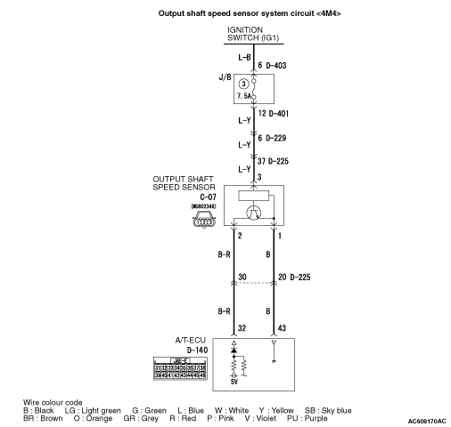
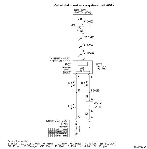


OPERATION
The output shaft speed sensor detects the speed of the direct planetary carrier, and sends
the information to the ECU as a pulse signal.
DIAGNOSIS CODE SET CONDITIONS
If the output pulse from the output shaft speed sensor has been lost for one second or
more while the vehicle is being driven, it is judged that there is an open circuit or short
circuit in the output shaft speed sensor, and diagnosis code No.P1767 (P0720) is set.
If the code No.P1767 (P0720) is set four times, the transmission will be fixed in 3rd
gear as a fail-safe measure. However, the transmission can be downshifted to 2nd gear by operating
the selector lever.
PROBABLE CAUSES
- Malfunction of output shaft speed sensor
- Malfunction of output shaft <4A/T>
- Malfunction of direct planetary carrier <5A/T>
- Damaged harness wires and connectors
- Malfunction of the A/T-ECU <4M4>
- Malfunction of the engine-A/T-ECU <6G7>
|
|
STEP 1. M.U.T.-III data list
|
|
|
Item 6: Output shaft speed sensor (Refer to data list reference table  ). ).
|
|
|
Q.
Is the check result normal?
|
|
|
 Intermittent malfunction (Refer to GROUP 00 - How to Cope with Intermittent
Malfunction ). Intermittent malfunction (Refer to GROUP 00 - How to Cope with Intermittent
Malfunction ).
|
|
|
|
|
|
 Go to Step 2. Go to Step 2.
|
|
|
|
|
|
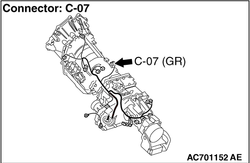
STEP 2. Connector check: C-07 output shaft speed sensor connector
|
|
|
Check for the contact with terminals.
|
|
|
Q.
Is the check result normal?
|
|
|
Go to Step 3.
|
|
|
|
|
|
Repair the defective connector.
|
|
|
|
|
|
STEP 3. Measure the resistance at output shaft speed sensor connector
C-07.
|
|
|
Disconnect the connector, and measure the resistance between terminal 1 and earth at the
wiring harness side.
|
|
|
OK: Continuity (Less than 2 Ω)
|
|
|
Q.
Is the check result normal?
|
|
|
Go to Step 9.
|
|
|
|
|
|
Go to Step 4.
|
|
|
|
|
|
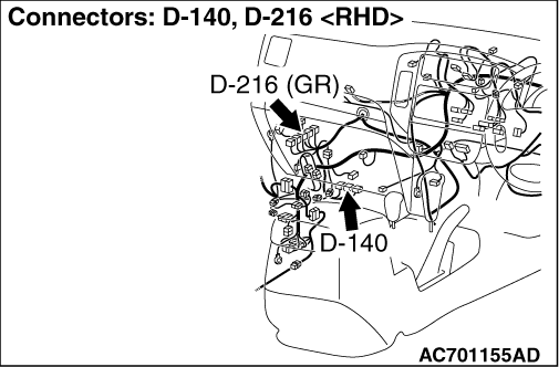
STEP 4. Measure the voltage at A/T-ECU connector D-140 <4M4> or
engine-A/T-ECU connector D-216 <6G7>.
|
|
|
(1)Connect output shaft speed sensor connector C-07.
|
|
|
(2)Turn the ignition switch to the ON position.
|
|
|
(3)Measure the voltage between A/T-ECU connector D-140 terminal No.43 <4M4> and
earth or engine-A/T-ECU connector D-216 terminal No.88 <6G7>.
OK: 0.5 V or less
|
|
|
Q.
Is the check result normal?
|
|
|
Go to Step 7.
|
|
|
|
|
|
Go to Step 5.
|
|
|
|
|
|
STEP 5. Connector check: D-140 A/T-ECU connector <4M4> or
D-216 engine-A/T-ECU connector <6G7>
|
|
|
Check for the contact with terminals.
|
|
|
Q.
Is the check result normal?
|
|
|
Go to Step 6.
|
|
|
|
|
|
Repair the defective connector.
|
|
|
|
|
|
STEP 6. M.U.T.-III data list
|
|
|
Item 6: Output shaft speed sensor (Refer to data list reference table ).
|
|
|
Q.
Is the check result normal?
|
|
|
Intermittent malfunction (Refer to GROUP 00 - How to Cope with Intermittent
Malfunction ).
|
|
|
|
|
|
Replace the A/T-ECU <4M4> or engine-A/T-ECU <6G7>.
|
|
|
|
|
|
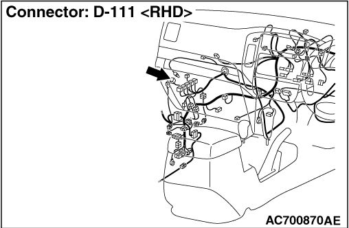
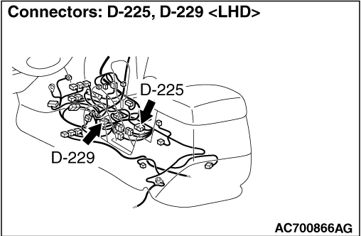
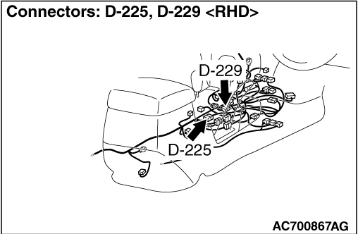
STEP 7. Connector check: D-225 intermediate connector, D-111 J/C (5) <6G7>, D-140 A/T-ECU connector <4M4> or
D-216 engine-A/T-ECU connector <6G7>
|
|
|
Check for the contact with terminals.
|
|
|
Q.
Is the check result normal?
|
|
|
Go to Step 8.
|
|
|
|
|
|
Repair the defective connector.
|
|
|
|
|
|
STEP 8. Check the harness between output shaft speed sensor connector
C-07 terminal No.1 and A/T-ECU connector D-140 terminal No.43 <4M4> or
engine-A/T-ECU connector D-216 terminal No.88 <6G7>.
|
|
|
Check the earth line for open circuit.
|
|
|
Q.
Is the check result normal?
|
|
|
Go to Step 6.
|
|
|
|
|
|
Repair the wiring harness.
|
|
|
|
|
|
STEP 9. Measure the voltage at output shaft speed sensor connector
C-07.
|
|
|
(1)Disconnect the connector, and measure the voltage between terminal 3 and earth
at the wiring harness side.
|
|
|
(2)Turn the ignition switch to the ON position.
OK: System voltage
|
|
|
Q.
Is the check result normal?
|
|
|
Go to Step 12.
|
|
|
|
|
|
Go to Step 10.
|
|
|
|
|
|
STEP 10. Connectors check: D-401 J/B connector, D-225 and
D-229 intermediate connector
|
|
|
Check for the contact with terminals.
|
|
|
Q.
Is the check result normal?
|
|
|
Go to Step 11.
|
|
|
|
|
|
Repair the defective connector.
|
|
|
|
|
|
STEP 11. Check the harness between output shaft speed sensor connector
C-07 terminal No.3 and junction block connector D-401 terminal No.12.
|
|
|
Check the power supply line for short or open circuit.
|
|
|
Q.
Is the check result normal?
|
|
|
Go to Step 6.
|
|
|
|
|
|
Repair the wiring harness.
|
|
|
|
|
|
STEP 12. Measure the voltage at output shaft speed sensor connector
C-07.
|
|
|
(1)Disconnect the connector, and measure the voltage between terminal 2 and earth
at the wiring harness side.
|
|
|
(2)Turn the ignition switch to the ON position.
OK: 4.5 - 4.9 V
|
|
|
Q.
Is the check result normal?
|
|
|
Go to Step 18.
|
|
|
|
|
|
Go to Step 13.
|
|
|
|
|
|
STEP 13. Measure the voltage at A/T-ECU connector D-140 <4M4> or
engine-A/T-ECU connector D-216 <6G7>.
|
|
|
(1)Disconnect output shaft speed sensor connector C-07.
|
|
|
(2)Turn the ignition switch to the ON position.
|
|
|
(3)Measure the voltage between A/T-ECU connector D-140 terminal No.32 <4M4> and
earth or engine-A/T-ECU connector D-216 terminal No.73 <6G7> and
earth.
OK: 4.5 - 4.9 V
|
|
|
Q.
Is the check result normal?
|
|
|
Go to Step 16.
|
|
|
|
|
|
Go to Step 14.
|
|
|
|
|
|
STEP 14. Connector check: D-225 intermediate connector, D-111 J/C
(5) <6G7>, D-140 A/T-ECU connector <4M4> or D-216 engine-A/T-ECU
connector <6G7>
|
|
|
Check for the contact with terminals.
|
|
|
Q.
Is the check result normal?
|
|
|
Go to Step 15.
|
|
|
|
|
|
Repair the defective connector.
|
|
|
|
|
|
STEP 15. Check the harness between output shaft speed sensor connector
C-07 terminal No.2 and A/T-ECU connector D-140 terminal No.32 <4M4> or
engine-A/T-ECU connector D-216 terminal No.73 <6G7>.
|
|
|
Check the output line for short circuit.
|
|
|
Q.
Is the check result normal?
|
|
|
Go to Step 6.
|
|
|
|
|
|
Repair the wiring harness.
|
|
|
|
|
|
STEP 16. Connector check: D-225 intermediate connector, D-111 J/C
(5) <6G7>, D-140 A/T-ECU connector <4M4> or D-216 engine-A/T-ECU
connector <6G7>
|
|
|
Check for the contact with terminals.
|
|
|
Q.
Is the check result normal?
|
|
|
Go to Step 17.
|
|
|
|
|
|
Repair the defective connector.
|
|
|
|
|
|
STEP 17. Check the harness between output shaft speed sensor connector
C-07 terminal No.2 and A/T-ECU connector D-140 terminal No.32 <4M4> or
engine-A/T-ECU connector D-216 terminal No.73 <6G7>.
|
|
|
Check the output line for open circuit.
|
|
|
Q.
Is the check result normal?
|
|
|
Go to Step 6.
|
|
|
|
|
|
Repair the wiring harness.
|
|
|
|
|
|
STEP 18. Measure the output wave pattern of the output shaft speed
sensor at A/T-ECU connector D-140 <4M4> or engine-A/T-ECU connector D-216 <6G7> (using
an oscilloscope).
|
|
|
(1)Shift the selector lever to the D range.
|
|
|
(2)Accelerate the vehicle to approximately 50 km/h (shift range; 3rd.)
|
|
|
(3)Connect an oscilloscope, and measure the voltage between A/T-ECU connector D-140 terminal
No.32 <4M4> and earth or engine-A/T-ECU connector D-216 terminal No.73 <6G7> and
earth.
OK: A wave pattern such as the one shown on (Check
Procedure Using an Oscilloscope) should be output, and the maximum value should be 4.8 V or
more and the minimum value should be 0.8 V or less. There should be no noise in the output wave
pattern.
|
|
|
Q.
Is the check result normal?
|
|
|
Go to Step 6.
|
|
|
|
|
|
Go to Step 19.
|
|
|
|
|
|
STEP 19. Connector check: D-140 A/T-ECU connector <4M4> or
D-216 engine-A/T-ECU connector <6G7>
|
|
|
Check for the contact with terminals.
|
|
|
Q.
Is the check result normal?
|
|
|
Go to Step 20.
|
|
|
|
|
|
Repair the defective connector.
|
|
|
|
|
|
STEP 20. Replace the output shaft speed sensor and then recheck the
diagnosis code.
|
|
|
(1)Replace the output shaft speed sensor.
|
|
|
(2)Test drive the vehicle.
|
|
|
(3)Check if the diagnosis code is set.
|
|
|
Q.
Is diagnosis code P1767 (P0720) set?
|
|
|
Go to Step 21.
|
|
|
|
|
|
The inspection is complete.
|
|
|
|
|
|
STEP 21. Check the output shaft <4A/T> or direct planetary
carrier <5A/T>.
|
|
|
Visually check the output shaft <4A/T> or direct planetary carrier <5A/T> for
damage.
|
|
|
Q.
Is the check result normal?
|
|
|
Eliminate the cause of the noise.
|
|
|
|
|
|
Replace the output shaft <4A/T> or direct planetary carrier <5A/T>.
|
|
|
|
)
)
)
)
)
)
)
)
)