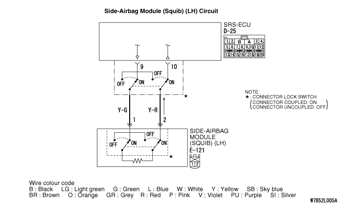
Code No.B1431:
Side-airbag squib (LH) open-circuited
| caution |
If diagnosis code B1431 is set in the SRS-ECU, always diagnose
the CAN bus lines.
|
OPERATION
- The SRS-ECU judges how severe a collision is by detecting signals from the
left and right side impact sensors. If the impact is over a predetermined level, the SRS-ECU
sends an ignition signal. At this time, if the side-airbag safing G-sensor is on, the SRS side-airbag
will inflate.
- The ignition signal is input to the side-airbag module to inflate the side-airbag.
DIAGNOSIS CODE SET CONDITIONS
This diagnosis code is set if there is abnormal resistance between the input terminals
of the side-airbag module (LH) (squib).
PROBABLE CAUSES
- Open circuit in the side-airbag module (LH) (squib) circuit
- Improper connector contact
- Malfunction of the SRS-ECU
|
|
STEP 1. M.U.T.-III CAN bus diagnostics
|
|
|
Use the M.U.T.-III to diagnose the CAN bus lines.
|
|
|
Q.
Is the check result normal?
|
|
|
 Go to Step 2. Go to Step 2.
|
|
|
|
|
|
 Repair the CAN bus lines (Refer to GROUP 54D, Diagnosis-Can Bus Diagnostic Chart Repair the CAN bus lines (Refer to GROUP 54D, Diagnosis-Can Bus Diagnostic Chart  ). ).
|
|
|
|
|
|
STEP 2. Check whether the diagnosis code is reset.
|
|
|
Check again if the diagnosis code is set.
|
|
|
(1)Erase the diagnosis code.
|
|
|
(2)Ignition: "LOCK" (OFF) position to "ON"
|
|
|
(3)On completion, check that the diagnosis code is not reset.
|
|
|
Q.
Is the diagnosis code set?
|
|
|
Go to Step 3.
|
|
|
|
|
|
There is an intermittent malfunction such as poor engaged connector(s) or open
circuit (Refer to GROUP 00, How to Cope with Intermittent Malfunction ).
|
|
|
|
|
|
STEP 3. Check the side-airbag module (LH).
|
|
|
(1)Disconnect the negative battery terminal.
|
|
|
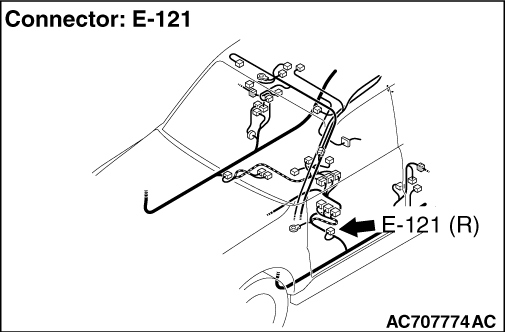
(2)Disconnect the side-airbag module (LH) connector E-121.
|
|
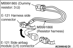
(3)Connect special tool dummy resistor (MB991865) to special tool resistor harness (MB991866).
(4)
| caution |
Do not insert a test probe into the terminal from its front side directly,
as the connector contact pressure may be weakened.
|
Insert special tool MB991866 into the E-121 harness side connector by backprobing.
(5)Connect the negative battery terminal.
(6)Erase the diagnosis code from memory, and then check the diagnosis code.
Q.
Is diagnosis code B1431 set?
Go to Step 4.
Replace the front seatback assembly (LH) (Refer to GROUP 52A, Front Seat ).
|
|
|
STEP 4. Resistance measurement between the SRS-ECU connector D-25
(terminal No.9 and 10) and the side-airbag module (LH) connector E-121 (terminal No.1 and 2).
|
|
|
(1)Disconnect the negative battery terminal.
|
|
|
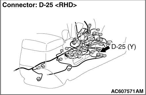
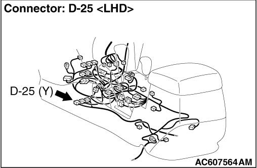
(2)Disconnect SRS-ECU connector D-25.
|
|
|
(3)
| danger |
To prevent the air bag from deploying unintentionally,
disconnect the side-airbag module (LH) connector E-121 to short the squib circuit.
|
Disconnect the side-airbag module (LH) connector E-121.
|
|
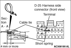
(4)
| caution |
Insert an insulator such as a cable tie to a depth of 4 mm or more, otherwise the short
spring will not be released.
|
Insert a cable tie [3 mm wide, 0.5 mm thick]
between terminals 9, 10
and the short spring to release the short spring.
(5)
| caution |
Do not insert a test probe into the terminal from
its front side directly, as the connector contact pressure may be weakened.
|
Check for continuity between the following terminals.
- SRS-ECU connector D-25 (terminal No.9) and the side-airbag module (LH) connector
E-121 (terminal No.1)
- SRS-ECU connector D-25 (terminal No.10) and the side-airbag module (LH) connector
E-121 (terminal No.2)
OK: Continuity (Less than 2 Ω)
Q.
Are the check results normal?
Go to Step 5.
Repair the harness wires between SRS-ECU connector D-25 (terminal No.9 and 10)
and side-airbag module (LH) connector E-121 (terminal No.1 and 2).
|
|
|
STEP 5.Check whether the diagnosis code is reset.
|
|
|
Q.
Is diagnosis code B1431 set?
|
|
|
Replace the SRS-ECU (Refer to ).
|
|
|
|
|
|
An intermittent malfunction is suspected (Refer to GROUP 00, How to Cope with
Intermittent Malfunction ).
|
|
|
|
)
)
)
)
)
)