Code No.C1382:
G-sensor malfunction (Low voltage)
Code No.C1383: G-sensor malfunction (High voltage)
|
|
| caution |
- If there is
any problem in the CAN bus lines, an incorrect diagnosis code may be set. Prior to this diagnosis,
diagnose the CAN bus lines (Refer to GROUP 54C, Trouble Code Diagnosis
 ). ).
- Before replacing the ECU, ensure that the communication circuit is normal.
|
|
|
|
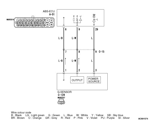
The G-sensor detects the acceleration level in the forward/reverse direction
of the vehicle, converts the signals into voltage signals and then sends that signal to the
ABS-ECU.
|
|
|
DIAGNOSIS CODE SET CONDITIONS
|
|
|
This diagnosis code will be set under the cases below.
|
|
|
Code No.C1382
- With diagnosis codes No. C1365 being not set, the input value from the G-sensor
is excessive low.
|
|
|
Code No.C1383
- With diagnosis codes No. C1365 being not set, the input value from the G-sensor
is excessive high.
|
|
|
- Damaged wiring harness or connector
- Malfunction of the G-sensor
- Malfunction of the ABS-ECU
|
|
|
STEP 1. M.U.T.-III CAN bus diagnosis.
|
|
|
Use M.U.T.-III to diagnose the CAN bus lines.
|
|
|
Q.
Is the check result normal?
|
|
|
 Go to Step 3. Go to Step 3.
|
|
|
|
|
|
 Repair the CAN bus line (Refer to GROUP 54C, CAN Bus Line Diagnostic Flow ).
Then go to Step 2. Repair the CAN bus line (Refer to GROUP 54C, CAN Bus Line Diagnostic Flow ).
Then go to Step 2.
|
|
|
|
|
|
STEP 2. Diagnosis code recheck after resetting CAN bus lines
|
|
|
Erase the diagnosis code.
|
|
|
Q.
Is the diagnosis code No.C1382 or No.C1383 set?
|
|
|
Go to Step 3.
|
|
|
|
|
|
The procedure is complete.
|
|
|
|
|
|
STEP 3. M.U.T.-III data list
|
|
|
Check the following service data (Refer to ).
|
|
|
Q.
Is the check result normal?
|
|
|
Go to Step 11.
|
|
|
|
|
|
Go to Step 4.
|
|
|
|
|
|
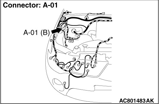
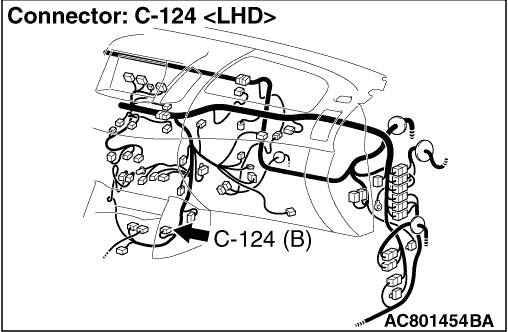
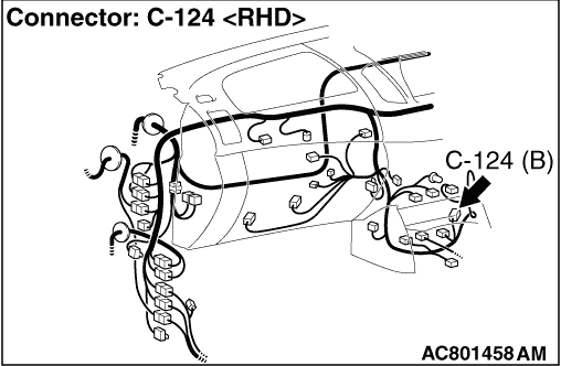
STEP 4. Connector check: A-01 ABS-ECU connector, C-15 intermediate
connector, C-124 G-sensor connector
|
|
|
Q.
Is the check result normal?
|
|
|
Go to Step 5.
|
|
|
|
|
|
Repair or replace it. Then go to Step 12.
|
|
|
|
|
|
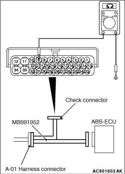
STEP 5. Resistance measurement at A-01 ABS-ECU connector
|
|
(1)Disconnect the A-01 ABS-ECU connector, and connect special tool ABS check harness (MB991952)
to the wiring harness-side connector.
| note |
Do not connect special tool ABS check harness (MB991952) to the ABS-ECU.
|
(2)Disconnect the C-124 G-sensor connector.
(3)Resistance between the A-01 ABS-ECU connector terminal No.9 and the body earth.
OK: No continuity
Q.
Is the check result normal?
Go to Step 6.
An short circuit may be present in the signal circuit. Repair the wiring harness
between the A-01 ABS-ECU terminal No.9 and the body earth. Then go to Step 12.
|
|
|
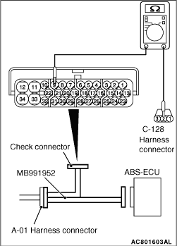
STEP 6. Resistance measurement at A-01 ABS-ECU connector and C-124
G-sensor connector
|
|
(1)Disconnect the A-01 ABS-ECU connector, and connect special tool ABS check harness (MB991952)
to the wiring harness-side connector.
| note |
Do not connect special tool ABS check harness (MB991952) to the ABS-ECU.
|
(2)Disconnect the C-124 G-sensor connector.
(3)Resistance between the A-01 ABS-ECU connector terminal No.9 and the C-124 G-sensor
connector terminal No.2.
OK: Continuity exists (2 Ω or less)
Q.
Is the check result normal?
Go to Step 7.
An open circuit may be present in the signal circuit. Repair the wiring harness
between the A-01 ABS-ECU terminal No.9 and the C-124 G-sensor connector terminal No.2. Then
go to Step 12.
|
|
|
STEP 7. Voltage measurement at C-124 G-sensor connector.
|
|
|
(1)Disconnect the C-124 G-sensor connector and A-01 ABS-ECU connector, and voltage
measurement to the wiring harness-side of C-124 G-sensor connector.
|
|
|
(2)Measure the voltage between terminal No.2 and body earth.
OK: Approximately 1 V or less
|
|
|
Q.
Is the check result normal?
|
|
|
Go to Step 8.
|
|
|
|
|
|
An short circuit may be present. Repair the wiring harness between the A-01 ABS-ECU
terminal No.9 and the C-124 G-sensor connector terminal No.2. Then go to Step 12.
|
|
|
|
|
|
STEP 8. Voltage measurement at C-124 G-sensor connector.
|
|
|
(1)Disconnect the C-124 G-sensor connector and A-01 ABS-ECU connector, and voltage
measurement to the wiring harness-side of C-124 G-sensor connector.
|
|
|
(2)Measure the voltage between terminal No.1 and body earth.
OK: Approximately 1 V or less
|
|
|
Q.
Is the check result normal?
|
|
|
Go to Step 9.
|
|
|
|
|
|
An short circuit may be present. Repair the wiring harness between the A-01 ABS-ECU
terminal No.6 and the C-124 G-sensor connector terminal No.1. Then go to Step 12.
|
|
|
|
|
|
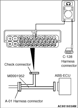
STEP 9. Resistance measurement at A-01 ABS-ECU connector and C-124
G-sensor connector
|
|
(1)Disconnect the A-01 ABS-ECU connector, and connect special tool ABS check harness (MB991952)
to the wiring harness-side connector.
| note |
Do not connect special tool ABS check harness (MB991952) to the ABS-ECU.
|
(2)Disconnect the C-124 G-sensor connector.
(3)Resistance between the A-01 ABS-ECU connector terminal No.6 and the C-124 G-sensor
connector terminal No.1.
OK: Continuity exists (2 Ω or less)
Q.
Is the check result normal?
Go to Step 10.
An open circuit may be present. Repair the wiring harness between the A-01 ABS-ECU
terminal No.6 and the C-124 G-sensor connector terminal No.1. Then go to Step 12.
|
|
|
STEP 10. Diagnosis code recheck
|
|
|
Erase the diagnosis code.
|
|
|
Q.
Is the diagnosis code No.C1382 or No.C1383 set?
|
|
|
Replace the G-sensor (Refer to ). Then go to Step
11.
|
|
|
|
|
|
Intermittent malfunction (Refer to GROUP 00 - How to Cope with Intermittent
Malfunction ).
|
|
|
|
|
|
STEP 11. Diagnosis code recheck
|
|
|
Erase the diagnosis code.
|
|
|
Q.
Is the diagnosis code No.C1382 or No.C1383 set?
|
|
|
Replace the ABS-ECU (Refer to ). Then go to Step
12.
|
|
|
|
|
|
Intermittent malfunction (Refer to GROUP 00 - How to Cope with Intermittent
Malfunction ).
|
|
|
|
|
|
STEP 12. Diagnosis code recheck
|
|
|
Erase the diagnosis code.
|
|
|
Q.
Is the diagnosis code No.C1382 or No.C1383 set?
|
|
|
Return to Step 1.
|
|
|
|
|
|
This diagnosis is complete.
|
|
|
|
)
)
)
)
)
)
)