Code No.C1280:
Motor fail-safe relay (short circuit)
|
|
| caution |
If there is any problem in
the CAN bus lines, an incorrect diagnosis code may be set. Diagnose the CAN bus lines before
the diagnosis codes (Refer to GROUP 54C - CAN Bus Diagnostics Table  ). ).
|
|
|
|
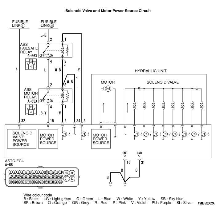
The ASTC-ECU contains the power supply circuit (terminal 15) for the motor. ACTS-ECU incorporates
a monitor to check if power is supplied to the motor for running.
|
|
|
DIAGNOSIS CODE SET CONDITIONS
|
|
|
This code is set when the power supply is normal but the ABS motor relay is ON even if
the ABS failsafe relay is turned OFF.
|
|
|
The most likely causes for this diagnosis code to set is:
|
|
|
- Damaged wiring harness or connector
- Malfunction of the hydraulic unit assembly (integrated with ASTC-ECU)
|
|
|
STEP 1. M.U.T.-III CAN bus diagnosis.
|
|
|
Use M.U.T.-III to diagnose the CAN bus lines.
|
|
|
Q.
Is the check result normal?
|
|
|
 Go to Step 3. Go to Step 3.
|
|
|
|
|
|
 Repair the CAN bus lines (Refer to GROUP 54C - CAN Bus Diagnostics Table ).
On completion, go to Step 2. Repair the CAN bus lines (Refer to GROUP 54C - CAN Bus Diagnostics Table ).
On completion, go to Step 2.
|
|
|
|
|
|
STEP 2. Diagnosis code recheck after resetting CAN bus lines.
|
|
|
(1)Turn the ignition switch to the "ON" position.
|
|
|
(2)Erase the diagnosis code.
|
|
|
(3)Turn the ignition switch to the "LOCK" (OFF) position.
|
|
|
(4)Turn the ignition switch to the "ON" position.
|
|
|
(5)Check if the diagnosis code is set.
|
|
|
(6)Turn the ignition switch to the "LOCK" (OFF) position.
|
|
|
Q.
Is the diagnosis code No.C1280 set?
|
|
|
Go to Step 3.
|
|
|
|
|
|
The procedure is complete.
|
|
|
|
|
|
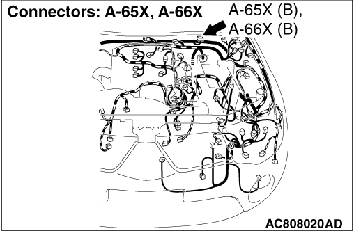
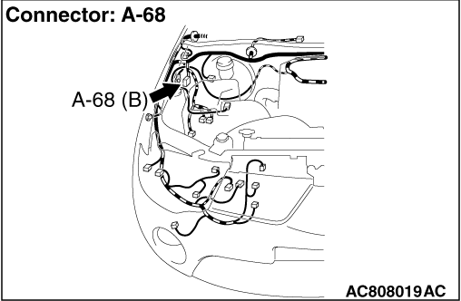
STEP 3. Connector check: A-68 ASTC-ECU connector, A-65X ABS motor
relay connector and A-66X ABS failsafe relay connector
|
|
|
Q.
Is the check result normal?
|
|
|
Go to Step 4.
|
|
|
|
|
|
Repair or replace the damaged component(s). Then go to Step 12.
|
|
|
|
|
|
STEP 4. ABS failsafe relay check
|
|
|
Refer to .
|
|
|
Q.
Is the check result normal?
|
|
|
Go to Step 5.
|
|
|
|
|
|
Repair it. Then go to Step 12.
|
|
|
|
|
|
STEP 5. ABS motor relay check
|
|
|
Refer to .
|
|
|
Q.
Is the check result normal?
|
|
|
Go to Step 6.
|
|
|
|
|
|
Repair it. Then go to Step 12.
|
|
|
|
|
|
STEP 6. Voltage measurement at A-66X ABS failsafe relay connector
|
|
|
(1)Disconnect the connector A-66X ABS failsafe relay connector, and measure the voltage
at the harness-side connector.
|
|
|
(2)Measure the voltage between the terminal No.2 and the body earth.
OK: System voltage
|
|
|
Q.
Is the check result normal?
|
|
|
Go to Step 7.
|
|
|
|
|
|
The open circuit may be present in the motor power supply circuit. Repair the
wiring harness between the fusible link No.22 and the A-66X ABS failsafe relay connector terminal
No.2. Then go to Step 12.
|
|
|
|
|
|
STEP 7. Voltage measurement at A-65X ABS motor relay connector
|
|
|
(1)Disconnect the connector A-66X ABS failsafe relay connector and A-65X ABS motor
relay connector, and measure the voltage at the harness-side connector.
|
|
|
(2)Ignition switch to the "ON" position.
|
|
|
(3)Measure the voltage between the A-65X ABS motor relay connector terminal No.2 and
body earth.
OK: 1 V or less
|
|
|
Q.
Is the check result normal?
|
|
|
Go to Step 8.
|
|
|
|
|
|
The short circuit may be present in the motor power supply circuit. Repair the
wiring harness between the A-65X ABS motor relay connector terminal No.2 and A-66X ABS failsafe
relay connector terminal No.4. Then go to Step 12.
|
|
|
|
|
|
STEP 8. Voltage measurement at A-65X ABS motor relay connector
|
|
|
(1)Disconnect the connector A-65X ABS motor relay connector and measure at the harness-side
connector.
|
|
|
(2)Disconnect the A-68 ASTC-ECU connector.
|
|
|
(3)Ignition switch to the "ON" position.
|
|
|
(4)Measure the voltage between the A-65X ABS motor relay connector terminal No.4 and
body earth.
OK: 1 V or less
|
|
|
Q.
Is the check result normal?
|
|
|
Go to Step 9.
|
|
|
|
|
|
The short circuit may be present in the motor power supply circuit. Repair the
wiring harness between the A-68 ASTC-ECU connector terminal No.15 and A-65X ABS motor relay
connector terminal No.4. Then go to Step 12.
|
|
|
|
|
|
STEP 9. Resistance measurement at A-65X ABS motor relay connector
|
|
|
(1)Disconnect the connector A-65X ABS motor relay connector and measure the harness-side
connector.
|
|
|
(2)Disconnect the A-68 ASTC-ECU connector.
|
|
|
(3)Measure the resistance between the A-65X ABS motor relay connector terminal No.1
and body earth.
OK: No continuity
|
|
|
Q.
Is the check result normal?
|
|
|
Go to Step 10.
|
|
|
|
|
|
The short circuit may be present in the circuit. Repair the wiring harness between
the A-68 ASTC-ECU connector terminal No.2 and A-65X ABS motor relay connector terminal No.1.
Then go to Step 12.
|
|
|
|
|
|
STEP 10. Resistance measurement at A-66X ABS failsafe relay connector
|
|
|
(1)Disconnect the connector A-66X ABS failsafe relay connector and measure the harness-side
connector.
|
|
|
(2)Disconnect the A-68 ASTC-ECU connector.
|
|
|
(3)Measure the resistance between the A-66X ABS failsafe relay connector terminal
No.1 and body earth.
OK: No continuity
|
|
|
Q.
Is the check result normal?
|
|
|
Go to Step 11.
|
|
|
|
|
|
The short circuit may be present in the circuit. Repair the wiring harness between
the A-68 ASTC-ECU connector terminal No.3 and A-66X ABS failsafe relay connector terminal No.1.
Then go to Step 12.
|
|
|
|
|
|
STEP 11. Check whether the diagnosis code is reset.
|
|
|
(1)Turn the ignition switch to the "ON" position.
|
|
|
(2)Erase the diagnosis code.
|
|
|
(3)Turn the ignition switch to the "LOCK" (OFF) position.
|
|
|
(4)Turn the ignition switch to the "ON" position.
|
|
|
(5)Check that the ABS warning lamp, Brake warning lamp, ASTC indicator lamp and ASTC
OFF indicator lamp goes out when the vehicle is driven at 10km/h or more.
|
|
|
(6)Check if the diagnosis code is set.
|
|
|
(7)Turn the ignition switch to the "LOCK" (OFF) position.
|
|
|
Q.
Is the diagnosis code No.C1280 set?
|
|
|
Replace the hydraulic unit assembly (integrated with ASTC-ECU) (Refer to ).
Then go to Step 12.
|
|
|
|
|
|
Intermittent malfunction (Refer to GROUP 00 - How to Cope with Intermittent
Malfunction ).
|
|
|
|
|
|
STEP 12. Check whether the diagnosis code is reset.
|
|
|
(1)Turn the ignition switch to the "ON" position.
|
|
|
(2)Erase the diagnosis code.
|
|
|
(3)Turn the ignition switch to the "LOCK" (OFF) position.
|
|
|
(4)Turn the ignition switch to the "ON" position.
|
|
|
(5)Check that the ABS warning lamp, Brake warning lamp, ASTC indicator lamp and ASTC
OFF indicator lamp goes out when the vehicle is driven at 10km/h or more.
|
|
|
(6)Check if the diagnosis code is set.
|
|
|
(7)Turn the ignition switch to the "LOCK" (OFF) position.
|
|
|
Q.
Is the diagnosis code No.C1280 set?
|
|
|
Go to Step 1.
|
|
|
|
|
|
This diagnosis is complete.
|
|
|
|
)
)
)