Code No.C1403: Transfer Shift Lever Switch System (Abnormal)
OPERATION
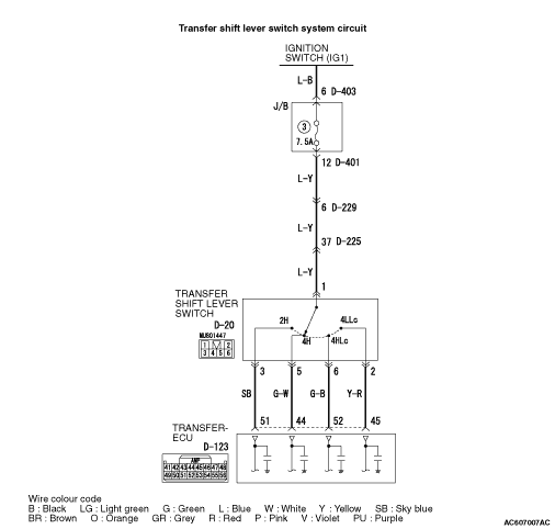
- System voltage is applied to the transfer shift lever switch (terminal No.1) when the ignition switch is turned ON.
- System voltage is applied to the transfer-ECU terminal No.51, 44, 52, or 45 when the transfer shift lever is in the "2H," "4H," "4HLc" or "4LLc." The transfer-ECU judges that the transfer shift lever is in the "2H," "4H," "4HLc" or "4LLc" when the system voltage is applied.
DIAGNOSIS CODE SET CONDITIONS
In the case that the input signal from the transfer shift lever switch is open or shorted, the code No.C1403 is set as the open circuit or the short circuit of the transfer shift lever switch system.
PROBABLE CAUSES
- Malfunction of the transfer shift lever switch
- Malfunction of the ignition switch
- Damaged harness wires and connectors
- Malfunction of the transfer-ECU
|
|
STEP 1. M.U.T.-III data list.
|
|
|
Item 41: Transfer shift lever position (Refer to data list reference table  ). ).
|
|
|
Q.
Is the check result normal?
|
|
|
 Intermittent malfunction (Refer to GROUP 00 - How to Cope with Intermittent Malfunction ). Intermittent malfunction (Refer to GROUP 00 - How to Cope with Intermittent Malfunction ).
|
|
|
|
|
|
 Go to Step 2. Go to Step 2.
|
|
|
|
|
|
STEP 2. Check the transfer shift lever switch.
|
|
|
Refer to .
|
|
|
Q.
Is the check result normal?
|
|
|
Go to Step 3.
|
|
|
|
|
|
Replace the transfer shift lever switch (Refer to ).
|
|
|
|
|
|
STEP 3. Measure the voltage at transfer shift lever switch connector D-20.
|
|
|
(1)Disconnect the connector, and measure the voltage between terminal No.1 and earth at the wiring harness side.
|
|
|
(2)Turn the ignition switch to the ON position.
OK: System voltage
|
|
|
Q.
Is the check result normal?
|
|
|
Go to Step 6.
|
|
|
|
|
|
Go to Step 4.
|
|
|
|
|
|
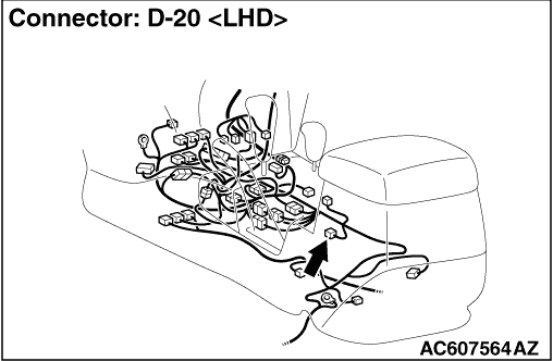
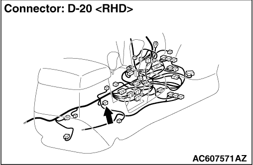
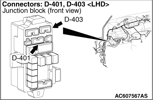
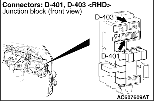
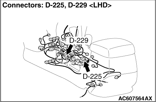
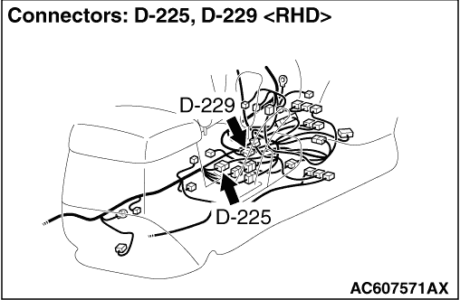
STEP 4. Connector check: D-401 J/B connector, D-225, D-229 intermediate connector, D-20 transfer shift lever switch connector.
|
|
|
Check for the contact with terminals.
|
|
|
Q.
Is the check result normal?
|
|
|
Go to Step 5.
|
|
|
|
|
|
Repair the defective connector.
|
|
|
|
|
|
STEP 5. Check the harness between J/B connector D-401 terminal No.12 and transfer shift lever switch connector D-20 terminal No.1.
|
|
|
Check the power supply line for short or open circuit.
|
|
|
Q.
Is the check result normal?
|
|
|
Go to Step 10.
|
|
|
|
|
|
Repair the wiring harness.
|
|
|
|
|
|
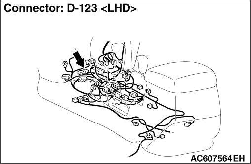
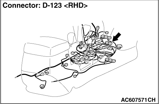
STEP 6. Measure the voltage at transfer-ECU connector D-123.
|
|
|
(1)Connect the transfer shift lever switch connector D-20.
|
|
|
(2)Turn the ignition switch to the ON position.
|
|
|
(3)Disconnect the D-123 transfer-ECU connector, and measure the voltage between the following terminals.
- No.51 and body earth (Transfer shift lever position: 2H)
- No.44 and body earth (Transfer shift lever position: 4H)
- No.52 and body earth (Transfer shift lever position: 4HLc)
- No.45 and body earth (Transfer shift lever position: 4LLc)
OK: System voltage
|
|
|
Q.
Is the check result normal?
|
|
|
Go to Step 9.
|
|
|
|
|
|
Go to Step 7.
|
|
|
|
|
|
STEP 7. Connector check: D-123 transfer-ECU connector, D-20 transfer shift lever switch connector.
|
|
|
Check for the contact with terminals.
|
|
|
Q.
Is the check result normal?
|
|
|
Go to Step 8.
|
|
|
|
|
|
Repair the defective connector.
|
|
|
|
|
|
STEP 8. Check the harness between transfer-ECU connector D-123 terminal No.51, No.44, No.52, No.45 and transfer shift lever switch connector D-20 terminal No.3, No.5, No.6, No.2.
|
|
|
Check the output line for short or open circuit.
|
|
|
Q.
Is the check result normal?
|
|
|
Go to Step 10.
|
|
|
|
|
|
Repair the wiring harness.
|
|
|
|
|
|
STEP 9. Connector check: D-123 transfer-ECU connector.
|
|
|
Check for the contact with terminals.
|
|
|
Q.
Is the check result normal?
|
|
|
Go to Step 10.
|
|
|
|
|
|
Repair the defective connector.
|
|
|
|
|
|
STEP 10. M.U.T.-III data list
|
|
|
Item 41: Transfer shift lever position (Refer to data list reference table ).
|
|
|
Q.
Is the check result normal?
|
|
|
Intermittent malfunction (Refer to GROUP 00 - How to Cope with Intermittent Malfunction ).
|
|
|
|
|
|
Replace the transfer-ECU.
|
|
|
|
)
)
)
)
)
)
)
)
)