FRONT PROPELLER SHAFT
FRONT PROPELLER SHAFT: 3F56A-DOJ75
Exploded View
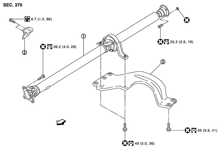
|
1. |
Front propeller shaft assembly |
2. |
Heat bracket |
3. |
Tunnel stay |
 : Vehicle front : Vehicle front |
|||||
|
Refer to Components for symbols in the figure. |
|||||
Removal and Installation
 REMOVAL
- 1.Remove the sub-muffler. Refer to Exploded View.
- 2.Remove the heat plate.
- 3.Remove the heat bracket.
- 4.Put matching marks onto propeller shaft flange yoke and front final drive and transmission companion flanges.
■ CAUTION ■
For matching marks, use paint. Never damage propeller shaft flange yoke and front final drive and transmission companion flange.- 5.Loosen front propeller shaft fixing bolts and nuts.
- When fixing the propeller shaft, never use a service tool inside the journal bearing to prevent damaging the joint seal.
- Tighten front propeller shaft assembly fixing bolt and nuts temporarily.
■ CAUTION ■
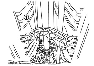
- 6.Remove the center bearing bracket and the tunnel stay (1).
- Never use power tools to remove or install the bolt on the tunnel stay.
- If the coating on the joint surface between the tunnel stay and the vehicle has peeled off, apply primer on the surface to prevent electric corrosion.
- Never use bolts other than those that are specified, otherwise electric corrosion occurs. Always use the specified bolt with its surface appropriately finished.
- Never reuse the bolt removed from the tunnel stay.
■ CAUTION ■
- 7.Remove front propeller shaft fixing bolts and nuts, and then remove the front propeller shaft assembly from the vehicle.
- Never bend the primary joint at an angle of more than 5°.
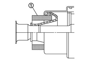
- Cover the joint boot on the primary joint with a cushion (1) or other appropriate materials to prevent deformation.
■ CAUTION ■
INSTALLATIONNote the following, and install in the reverse order of removal.
- Align the alignment mark when installing the propeller shaft assembly in the companion flange of the final drive.
- When installing the front propeller shaft assembly in the transmission, cover the boot on the primary joint with a cushion or other appropriate materials to prevent deformation.
- After assembly, perform a driving test to check propeller shaft vibration. If vibration occurred, separate propeller shaft from final drive. Reinstall companion flange after rotating it by 90, 180, 270 degrees. Then perform driving test and check propeller shaft vibration again at each point.
- Never use power tools to remove or install the bolt on the tunnel stay.
- If the coating on the joint surface between the tunnel stay and the vehicle has peeled off, apply primer on the surface to prevent electric corrosion.
- Never use bolts other than those that are specified on the tunnel stay, otherwise electric corrosion occurs. Always use the specified bolt with its surface appropriately finished.
- Never reuse the bolt removed from the tunnel stay.
Inspection
PROPELLER SHAFT RUNOUTCheck propeller shaft runout at measuring point with a dial indicator. If runout exceeds specifications, replace propeller shaft assembly. For measuring point, refer to Inspection (GT-R certified NISSAN dealer).
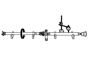
| Limit | |
| Propeller shaft runout | : Refer to Propeller Shaft Runout (GT-R certified NISSAN dealer). |
JOURNAL AXIAL PLAY- As shown in the figure, while fixing yoke on one side, check axial play of joint. If it is outside the standard, replace propeller shaft assembly.
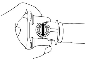
Standard Journal axial play : Refer to Journal Axial Play (GT-R certified NISSAN dealer).
■ CAUTION ■
Never disassemble joints.
CENTER BEARINGCheck center bearing for noise and damage. If noise or damage is detected, replace propeller shaft assembly.
■ CAUTION ■
Never disassemble center bearing.