MAIN PROPELLER SHAFT
MAIN PROPELLER SHAFT: 2F71A-VL101
Exploded View
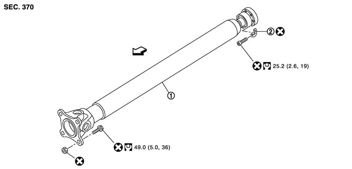
|
1. |
Main propeller shaft assembly |
2. |
Plain washer |
|
|
 : The front of vehicle : The front of vehicle |
|||||
|
Refer to Components in GI section for the symbols shown in the figure. |
|||||
Removal and Installation
 REMOVAL
- 1.Remove the front propeller shaft assembly. Refer to Exploded View (GT-R certified NISSAN dealer).
- 2.Put matching marks on the joint between the main propeller shaft assembly and the companion flanges of the output shaft and the transmission.
■ CAUTION ■
Use paint for alignment marks to avoid scratching the surface. - 3.Remove the bolts and nuts from the main propeller shaft.
■ CAUTION ■
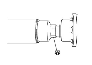
When rotating the main propeller shaft, use a spanner or a suitable tool on the hex end (A) of the rebro joint and rotate the shaft in the clockwise direction as viewed from the crankshaft (in the counterclockwise direction, as viewed from the back of vehicle). - 4.Install propeller shaft protector (commercial service tool) to main propeller shaft. Then remove the main propeller shaft together with the installed propeller shaft tube protector from the vehicle.
- Install the propeller shaft protector in the carbon area of the main propeller shaft.
- Never bend the secondary joint at the angle of more than 8.5°.
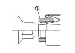
- Cover the joint boot on the primary joint with a cushion (1) or other appropriate materials to prevent deformation.
■ CAUTION ■
INSTALLATIONNote the following, and install in the reverse order of removal.
- Align matching marks when installing the main propeller shaft assembly on the companion flange. ■ CAUTION ■When installing the main propeller shaft assembly in the transmission, install propeller shaft protector (commercial service tool) in the carbon area of the main propeller shaft assembly.
- Perform a test drive to check that there is no runout on the propeller shaft after installation. Separate the main propeller shaft and the transmission assembly, if runout is detected. Rotate the companion flange 60° and reinstall it. Perform a test drive to inspect runout.
- If the main propeller shaft assembly or the transmission is replaced, assemble these parts in the following procedure.
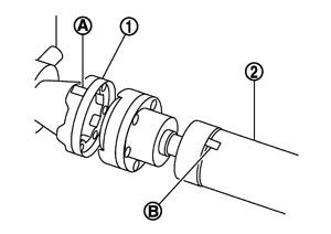
- 1.Position main propeller shaft assembly and the transmission so that the matching mark (B) on the main propeller shaft assembly (2) comes as close to the matching mark (A) on the companion flange of the transmission (1) as possible, with the matching mark positioned upward.
- 2.Tighten the bolts and nuts on the transmission and the main propeller shaft to the specified torque.
■ CAUTION ■
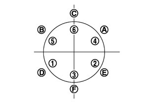
Tighten the bolts as per the following order. | Tightening procedure | Order |
| Temporary | 1 → 2 → 3 → 4 → 5 → 6 |
| Final | A → B → C → D → E → F |
Inspection
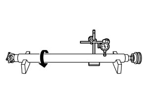
MAIN PROPELLER SHAFT RUNOUTCheck propeller shaft runout at measuring points with a dial indicator. If runout exceeds specifications, replace propeller shaft assembly. For measuring point, refer to Inspection (NHPC).
| Limit | |
| Main propeller shaft runout | : Refer to Propeller Shaft Runout (NHPC). |
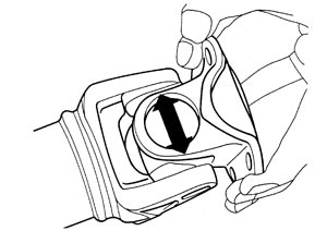
JOURNAL AXIAL PLAY- Check the play by moving the joint of the main propeller shaft in the direction shown by the arrow in the figure. Replace the main propeller shaft assembly if necessary.
Standard Journal axial play : Refer to Journal Axial Play (NHPC). - Check the main propeller shaft for bend and damage. Replace the main propeller shaft assembly if necessary. ■ CAUTION ■Never disassemble the joint.